Clockwork PicoCalc · Volume 3
PicoCalc Volume 3 — The Pico Module Family
Every Pico 1, Pico 2, RP2354, and Pimoroni footprint-compatible module — variants, swaps, decision matrix
Contents
1. About this Volume
This volume is the engineer’s reference for the swappable compute modules that fit the PicoCalc’s 2.54 mm Pico-pinout socket. Every Raspberry Pi-branded variant from the Pico (RP2040) family through the Pico 2 (RP2350) family is covered, plus pin-compatible third-party boards (Pimoroni Pico Plus 2 et al), the RP2354 stacked-flash footnote, and the procedure for hot-swapping modules without tools or firmware reconfiguration. The 3D-printable rear-back gallery for keeping multiple modules ready-to-go is in §3.5.
For adapters that present a Pico-shape socket on top of a different SoC (Pi Zero 2 W via ZeroCalc; Luckfox Lyra), see Volume 8 and Volume 9 respectively. Schematic-level treatment of those adapters is in Volume 7.
2. Every Raspberry Pi Pico Variant That Fits the Socket
The Pico socket on the ClockworkPi v2.0 carrier is a pair of 2.54 mm female headers in the standard Raspberry Pi Pico pinout. Any board that respects that pinout — including the official Raspberry Pi Pico families and their major Pico-footprint clones — will fit and boot. The catch is that not every variant exposes the same capabilities, and the firmware ecosystem you draw from is usually keyed to which silicon and which radio the module carries.
This chapter walks through every realistic option, what is actually different, and which of those differences will affect day-to-day use on the PicoCalc.
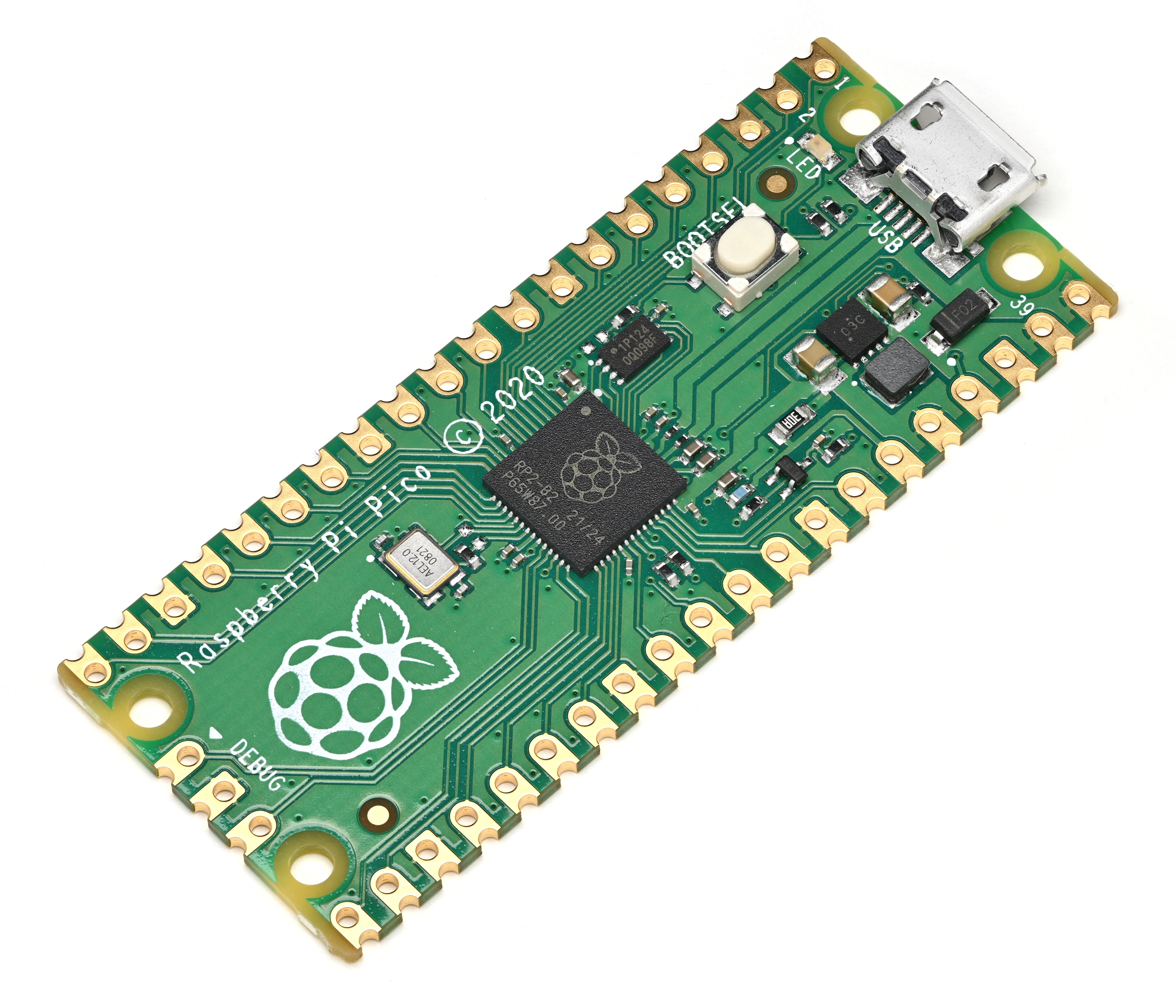
Figure 2.1 — Raspberry Pi Pico (RP2040). File:Raspberry Pi Pico oblique.jpg by Phiarc. License: CC BY-SA 4.0. Via Wikimedia Commons.
2.1 The Pico 1 family (RP2040)
The original Pico shipped in January 2021 and launched a family of four Raspberry Pi-branded variants over the next two years. Functionally they all use the same RP2040 silicon — the differences come down to whether headers ship pre-soldered and whether a wireless radio is fitted.
Pico (original). The bare board with castellated edges and unsoldered through-hole pads. Two cores of Cortex-M0+ at 133 MHz, 264 KB SRAM, 2 MB on-board QSPI NOR flash. No radio. No headers — you have to solder pin headers (or a pair of female sockets) yourself before it will fit the PicoCalc carrier.
Pico H. Identical silicon to the original Pico, but with factory-soldered male headers and a smaller 3-pin SM03B-SRSS-TB debug connector (replacing the three solder pads on the original). Functionally identical to a Pico that you’ve soldered yourself; the only practical difference is convenience and the keyed debug connector.
Pico W. Same RP2040 silicon, plus an Infineon CYW43439 module added for 2.4 GHz Wi-Fi 4 (802.11n) and Bluetooth LE 5.2. The CYW43439 occupies what was previously the on-board user LED’s location — the LED is now driven by the CYW43439 itself, not by a standard GPIO. The added antenna pushes the debug header up to the centre of the board. No factory headers.
Pico WH. A Pico W with factory-soldered male headers — this is the variant most people actually want for PicoCalc duty if they’re staying on Pico 1, because it adds wireless without requiring any soldering.
What this means in practice on the PicoCalc:
- Any Pico 1 variant fits the socket. If headers are not pre-soldered, you have to do it yourself; the carrier will not accept a bare castellated board.
- A Pico W or Pico WH adds Wi-Fi and BLE without any other changes. Pico SDK builds need
PICO_BOARD=pico_w. The on-board LED is a CYW43439 GPIO and is driven through the SDK’scyw43_arch_*API, notgpio_put(). - The 264 KB SRAM is the binding constraint on most projects — it cannot hold a full 320×320 16-bit frame buffer (200 KB) alongside a meaningful program. C drivers either render in horizontal stripes (8–16 lines per pass) or use the carrier’s 8 MB PSRAM as the frame buffer.
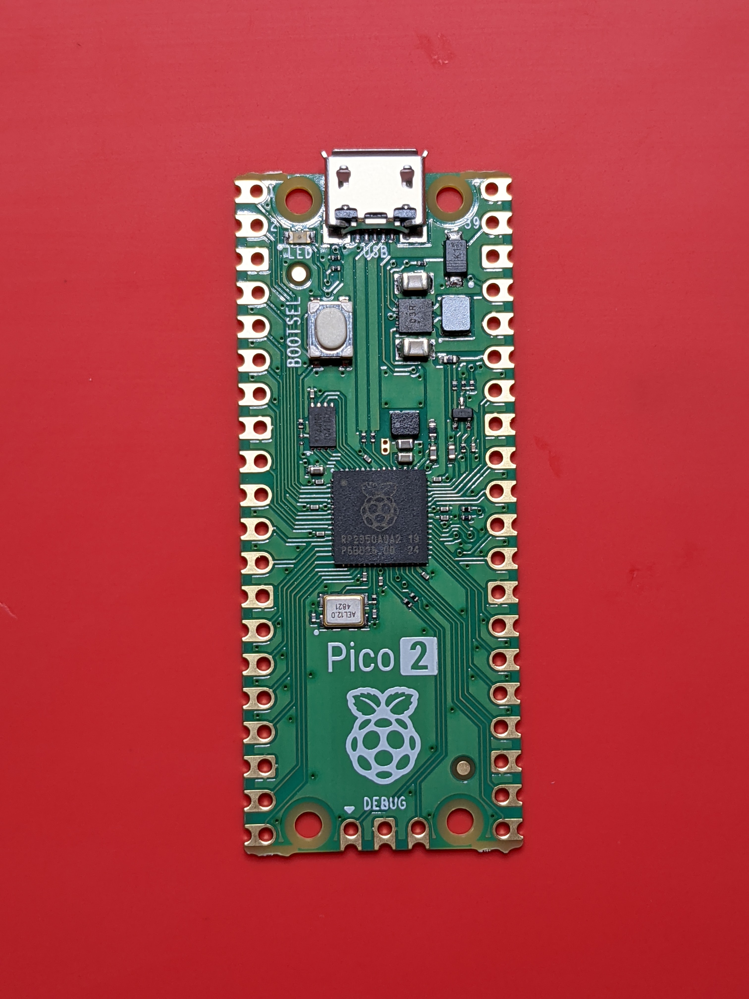
Figure 2.2 — Raspberry Pi Pico 2 (RP2350). File:Top view of a Raspberry Pi Pico 2 microcontroller board.jpg by Profpcde. License: CC0. Via Wikimedia Commons.
2.2 The Pico 2 family (RP2350)
Raspberry Pi launched the Pico 2 in August 2024 built around the new RP2350 SoC. The wireless variant followed in November 2024, and pre-soldered-header SKUs came shortly after. Functionally there are again four variants in the family — same combinatorics as Pico 1 (with/without headers, with/without radio).
Pico 2. RP2350A in QFN-60. Two Cortex-M33 cores at up to 150 MHz plus two Hazard3 RISC-V cores in the same package — you choose which pair to run at boot, never both architectures at once. 520 KB SRAM, 4 MB QSPI flash on-board, TrustZone-M security extensions, an FPU on each M33, a dedicated XIP+PSRAM bus, and additional PIO state machines compared to RP2040. No radio. No headers.
Pico 2 H. Identical silicon, factory-soldered male headers, JST-SM03B debug connector. The “default convenience” Pico 2.
Pico 2 W. RP2350 + Infineon CYW43439 for Wi-Fi 4 + BLE 5.2 — same radio as Pico W, just paired with the new SoC. Released November 2024, $7. The CYW43439’s specs limit it to 2.4 GHz Wi-Fi 4 and BLE 5.2 — the same ceiling as Pico W.
Pico 2 WH. Pico 2 W with factory-soldered male headers. Best out-of-the-box experience for PicoCalc — drops into the socket, adds wireless, no soldering.
What this means in practice on the PicoCalc:
- All Pico 2 variants need Pico SDK 2.x or newer. Older 1.x SDKs do not know about RP2350.
PICO_BOARDbecomespico2,pico2_wdepending on radio. The samecyw43_arch_*API drives the wireless on Pico 2 W.- 520 KB SRAM does hold a full 200 KB frame buffer with substantial program state alongside. This is the single biggest day-to-day win over Pico 1 for graphics-heavy work — entire emulator cores, full-screen UI frameworks, and double-buffered rendering all become straightforward.
- The FPU dramatically speeds anything that uses floating-point math — the graphing-calculator playbook in Chapter 21 is a different experience on a Pico 2.
- The architectures are interchangeable at flash time, not at run time. You pick Arm or RISC-V when you build the UF2; you cannot switch on the fly. Practically, almost all PicoCalc software is built for Arm — RISC-V support is improving but still has gaps in HAL libraries.
2.3 Pico-footprint third-party boards
The Raspberry Pi Pico’s pinout is now a de facto footprint that several third parties have cloned with extras stacked on top. The two most relevant for PicoCalc are:
Pimoroni Pico Plus 2 / Pico Plus 2 W. Same shape and pinout as the Pico 2, but with USB-C instead of micro-USB, 8 MB on-module PSRAM, 16 MB on-module flash (versus the Pico 2’s 4 MB), a Qw/ST I²C connector, an SP/CE SPI/serial connector, and a debug connector. The “W” version adds the same CYW43439 radio as Pico 2 W. Released March 2025. Pin-compatible with the Pico 2 — drops into the PicoCalc socket without modification, but the USB-C port faces the rear-grill cutout instead of the micro-USB cutout.
Adafruit Feather RP2350. Different footprint (Feather form factor) — does not drop into the PicoCalc socket without an adapter PCB. Mentioned here only because it tends to come up in searches; ignore it for PicoCalc unless you’re designing a custom carrier.
When the Pimoroni Plus 2 is in the socket, the PicoCalc treats it as a Pico 2 — PICO_BOARD=pico2_plus (or pico2_plus_w for the wireless version) is the right SDK target. The on-module PSRAM is in addition to the carrier’s 8 MB chip; the two coexist (the Pimoroni PSRAM is on a different chip-select), but most software targets only one or the other.
2.4 The RP2354 / “stacked-flash” footnote
In mid-2025 Raspberry Pi announced the RP2354, a pin-compatible variant of RP2350 with Winbond W25Q16JVWI 2 MB QSPI NOR flash stacked in-package. It’s mostly aimed at OEMs that want to drop a single chip into a board instead of routing flash externally. As of this writing, no Raspberry Pi-branded Pico product uses RP2354 — the Pico 2 and Pico 2 W still use RP2350A with separate QSPI flash. Third-party Pico-shaped boards using RP2354 will appear over time; functionally they are RP2350 with built-in flash and no other behavioural differences.
2.5 How to tell which module you have
Three quick ways:
- Read the silkscreen on the module itself. The original Pico says “Raspberry Pi Pico” with the year (©2021 = Pico 1). Pico 2 says “Raspberry Pi Pico 2” with ©2024. The wireless variants add “+W” or have the visible CYW43439 module on the board.
- Look for the antenna trace. Pico W and Pico 2 W both have a printed inverted-F antenna at one end of the board, plus an unpopulated U.FL footprint for an external antenna in some revisions.
- From software: on a running Pico, query
pico_get_unique_board_id()andrp2040_chip_version()(orrp2350_chip_version()) — but if you can already run code, you usually already know which board it is.
2.6 Why upgrade from Pico 1 to Pico 2
Concrete reasons that move the needle on the PicoCalc:
- Frame-buffer-heavy work fits in SRAM. A 320×320×16-bit buffer is 200 KB, leaving ~320 KB on a Pico 2 for code and state — comfortable. On a Pico 1, that buffer plus a meaningful program does not fit at all; you must stripe-render or use the carrier’s PSRAM.
- Floating-point math. Symbolic-math libraries, graphing-calculator-class plotting, audio synthesis with envelopes and LFOs, and signal-processing code all benefit from the FPU.
- Wireless tools. Picoware and similar wireless-focused firmware target Pico 2 W (or sometimes Pico W) — they do not run on a non-wireless Pico.
- Bigger flash. 4 MB versus 2 MB makes the difference between fitting a substantial PicoMite program library or MicroPython runtime + scripts and constantly running out of room.
- More PIO. Three PIO blocks instead of two, with twelve state machines total (RP2040 had eight). Useful when you’re driving multiple parallel busses or want a logic analyzer + display + WiFi-co-processor I/O all running at once.
2.7 Why stay on Pico 1
Equally legitimate reasons to keep the original:
- Most factory firmware was written for Pico 1. The default ClockworkPi multi-boot bundle, the NES emulator UF2 in the factory image, and several smaller community apps target RP2040 first. Pico 2 ports either follow later or never arrive.
- uLisp’s PicoCalc port is RP2040-specific as of v1.1; an RP2350 build is on the roadmap but not the current default.
- Lower power draw. Pico 1 idles around 25–30 mA. Pico 2 with FPU active is closer to 35–45 mA. Battery life on the same pair of 18650 cells is about 15–25% longer on Pico 1 for text/REPL workloads.
- Cheaper. Pico H is $5; Pico 2 H is $5 too at MSRP, but in practice retail markup keeps Pico 1 cheaper through most channels.
- Mature toolchain. SDK 1.x is rock-solid for Pico 1; the same SDK 2.x that supports Pico 2 also supports Pico 1, so this is mostly a “no benefit to upgrade for text apps” point.
3. The Pico Variant Decision Matrix
This chapter brings the previous chapter’s variants into a single decision-oriented view. The matrix is organized by what you intend to do with the PicoCalc — pick a use-case row, then pick a column based on what you have on hand.
3.1 Use-case-driven pick
| Use case | Best Pico variant | Acceptable substitutes | Avoid |
|---|---|---|---|
| BASIC / text / PicoMite calculator | Pico H | Pico 2 H, any other variant | none |
| MicroPython REPL + small scripts | Pico 2 H | Pico H, Pico 2 W | none |
| MicroPython with WiFi (web client) | Pico 2 W (WH) | Pico WH | non-wireless variants |
| Full-screen graphical apps (LVGL etc.) | Pico 2 H | Pico 2 W, Pimoroni Plus 2 | Pico 1 (stripe-only) |
| NES emulation | Pico 2 H | Pico H (with stripe rendering) | none, both run |
| Game Boy / GBC emulation | Pico 2 H | Pimoroni Plus 2 | Pico 1 (too slow) |
| GBA / SNES emulation | none — see Doc 3 (Pi Zero) | — | all Pico variants |
| PICO-8 fantasy console | none — see Doc 3 (Pi Zero) | — | all Pico variants |
| Sub-GHz hacking (CC1101 + nRF905) | Pico 2 H or Pico H | both work; Pico 2 has more PIO | none |
| WiFi pentest / Picoware | Pico 2 W | Pico W | non-wireless variants |
| LoRa-APRS | Pico 2 H | Pico H, Pico 2 W | none |
| WSPR beacon (TX through external module) | Pico 2 H | any other variant | none |
| CW keyer / Morse decoder | Pico H | any other variant | none |
| Logic analyzer / protocol probe | Pico 2 H | Pico H | none |
| Pocket Linux | none — see Doc 3 / Doc 4 | — | all Pico variants |
3.2 Concrete decision tree
If you are buying for the first time and do not yet own any module:
- Will you ever do anything that needs WiFi or BLE — even MicroPython HTTP clients, OTA updates, Picoware, MQTT?
- Yes → buy a Pico 2 WH. It is the most-capable single module, $7-ish, fits the socket without soldering, and runs every wireless and non-wireless workload.
- No → continue.
- Are most of your projects text/REPL or BASIC, with no need for full-frame graphics or floating-point math?
- Yes → buy a Pico H for $5. The mature ecosystem will run faster on the simpler chip and battery life will be slightly better.
- No → buy a Pico 2 H ($5 MSRP). The 520 KB SRAM and FPU make it the right default for graphical work.
If you already own a Pico H or Pico WH and want to know whether to upgrade:
- Do any of your active projects fail because you ran out of SRAM, ran out of flash, or wanted faster floating-point?
- Yes → upgrade to Pico 2 (matched to wireless / non-wireless).
- No → don’t upgrade. The socket means you can swap later in under a minute.
3.3 Mixing variants — keep more than one ready
The killer feature of the socketed module is that swapping takes 30–60 seconds and no tools. A reasonable middle path is to own two modules and swap based on the project:
- Pico H + Pico 2 WH. $5 + $7 = $12 total. Covers every workload between them. Pico H for BASIC and CW; Pico 2 WH for everything graphical or wireless. This is the “simple two-module bench” and the recommended starting point for most owners.
- Pico 2 H + Pico 2 WH. Both RP2350; one with radio, one without. Slight savings on idle current when you don’t need WiFi, and slightly more SRAM available because the CYW43 driver is not loaded.
- Pico H + Pico WH + Pico 2 WH. The “complete Raspberry Pi roster” — useful if you want to actively benchmark or develop firmware that has to work across all four families.
Whichever combination you keep, store the spare in an anti-static bag and keep a printed label on it (or use one of the rear-back designs in §3.5 that has a built-in module label).
3.4 Hot-swap procedure
Swapping the module on a powered-off PicoCalc takes under a minute:
- Power off by long-pressing the power button for ~3 seconds. Verify the screen is fully dark.
- Disconnect USB-C if attached.
- Open the rear shell. Four hex screws around the perimeter (2.5 mm hex key included with the kit). The rear comes off in one piece; the batteries stay in their holder on the rear half.
- Pry the Pico module out of its socket. Use even pressure on both ends — a small flat-head screwdriver under one end, then the other. Pry vertically; the pins are 2.54 mm and bend easily if you tilt.
- Verify orientation of the new module. The Pico’s USB connector points toward the rear grill of the PicoCalc case (the cutout is at the top edge, away from the keyboard). The DigitalDreams forum thread #17456 has a corrected pinout diagram if you want to triple-check; the kit’s silkscreen on the carrier shows the orientation as well.
- Seat the new module straight down into the socket. Both rows of pins should engage simultaneously. Press evenly until the body of the module sits flush with the spacer.
- Re-attach the rear shell. Don’t over-tighten the screws — the case is ABS and the screw bosses strip easily.
- Power on. First boot will land in whatever firmware is currently flashed on the new module. If you want to use the SD multi-boot, hold Up, F1, or F5 while powering on.
The first time you power on a Pico that has no firmware (a brand-new module), the PicoCalc will fall straight into BOOTSEL mode and the rear-grill USB-C will appear as a mass-storage drive (RPI-RP2 for Pico 1, RP2350 for Pico 2). Drag the UF2 you want onto it — typically bootloader_pico.uf2 or bootloader_pico2.uf2 from the UF2 Loader project, which gets you the SD multi-boot menu (see Chapter 7).
3.5 3D-printable rear backs for module swap
The kit’s stock rear shell is an ABS plastic clamshell that screws closed with four bolts. It works, but it makes module swapping a four-screw operation every time. The community has produced a number of replacement backs that solve various pain points; there are a couple of dozen STLs in 05-resources/3D Print Files/ of this project tree, and each is keyed to a particular module or use case.
The naming convention used in the project’s STL set is:
B05PCO.stl— back for Pico (1 or 2, non-wireless).B05ESP.stl— back for Pico + ESP-01S add-on at the side header (extra clearance and antenna cutout).B05LYP.stl— back for Luckfox Lyra Plus.B05LYR.stl— back for Luckfox Lyra (base or B variants).B05LYU.stl— back for Luckfox Lyra Ultra.B05LYC.stl(B04LYC.stl for the v0.4 carrier) — back for Lyra Console-style with extra port cutouts.B05XXXX.stl— generic blank for custom modifications.BTM4006.stl— battery-tray-style back with full 18650 access without a screwdriver.
Print settings that work in practice:
- Material: PETG is the best all-around. ABS matches the kit’s material but warps during printing without an enclosed printer. PLA prints fine but softens above ~55 °C — bad if the case lives in a car or a sunny window.
- Layer height: 0.20 mm. The hex-screw bosses and the side-header cutout are the only fine features; 0.20 mm captures them cleanly.
- Walls / infill: 4 walls, 25% gyroid infill. The case is structural; thin walls flex too much.
- Orientation: print with the inside-facing surface on the bed. The screw bosses hang off the print otherwise and need supports.
- Supports: the standard back doesn’t need any. The Pico Probe / ESP-01 backs need supports under the connector cutouts — use tree supports if your slicer offers them.
- Tolerances: the screw bosses are designed for M2.5 self-tapping, same hardware that ships with the kit. The hex-key socket on the kit driver is a slightly oversized M2.5 — a 0.1 mm boss diameter undersize on the print works well.
A practical workflow if you swap modules often:
- Print two backs, one for each module you keep ready (e.g.,
B05PCO.stlfor Pico H and a second copy for Pico 2 WH). - Cut a small label sticker for each (a Brother P-touch with 9 mm tape works well), stick it inside the rear shell, and keep the matching module screwed in to its dedicated back at all times.
- The “swap” then becomes: unscrew the four bolts on the current back, swap backs (which has the module already seated and screwed in), fasten, and you’re done — under 30 seconds.