M5Stack Cardputer ADV · Volume 2
M5Stack Cardputer ADV Volume 2 — Hardware Deep Dive
Stamp-S3A module + ST7789V2 display + TCA8418 keyboard scanner + ES8311 audio + BMI270 IMU + IR + power subsystem
2.1 About this volume
Vol 2 walks the Cardputer ADV hardware at functional-block level. Cross-references: Vol 3 carries the per-pin pinout (the interface outside the box); Vol 4 carries the module ecosystem (what you can plug into the box); Vol 5 carries the LoRa Cap separately because it’s the flagship companion.
Disclosure on depth: M5Stack does not publish a full Cardputer ADV schematic PDF. This volume walks the design pattern using vendor docs (docs.m5stack.com), the published mechanical Structure Files PDF, chip datasheets for the named components, and community teardowns. Specific component values (resistor values for pull-ups, capacitor sizes, exact PCB-trace lengths) are not published; this volume describes the design at functional-block level instead. Where vendor docs or teardown photos pin down a specific part number, this volume cites it; everywhere else, the description is “an N-bit ADC for battery voltage” rather than “an MCP3424.”
2.2 The Stamp-S3A module — ESP32-S3FN8
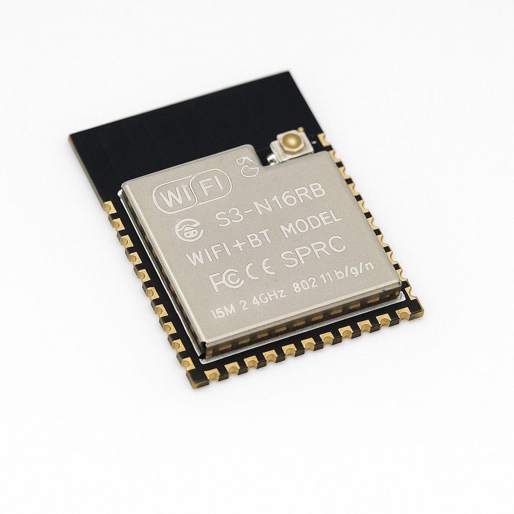
Figure 2.1 — ESP32-S3 SoC. Photo via web image search.
The Cardputer ADV is built around the Stamp-S3A — M5Stack’s compact ESP32-S3 module form factor. The module encloses an ESP32-S3FN8 chip + supporting passives + an antenna trace + a module shield can.
2.2.1 SoC specs
The ESP32-S3FN8 is Espressif’s ESP32-S3 silicon with an 8 MB SPI flash sized for typical Arduino + small-data workloads:
Table 1 — The ESP32-S3FN8 is Espressif's ESP32-S3 silicon with an 8 MB SPI flash sized for typical Arduino + small-data workloads
| Parameter | Value | Notes |
|---|---|---|
| CPU | Xtensa LX7 dual-core @ 240 MHz | LX7 not LX6 — incompatible binary with classic ESP32 |
| RAM | 512 KB SRAM | No PSRAM on this SKU (FN8 = bare module without external PSRAM) |
| Flash | 8 MB external SPI flash | Mapped into XIP region; firmware + SPIFFS / LittleFS partitions live here |
| Wi-Fi | 2.4 GHz only, 802.11 b/g/n (Wi-Fi 4) | No 5 GHz. Hard silicon limit. |
| Bluetooth | BT 5.0 LE only | No BT classic. Hard silicon limit on S3. |
| USB | Native USB-OTG full-speed (12 Mbps) | No UART bridge chip needed; bootloader entry via native USB-DFU |
| Crypto | Hardware AES-128/192/256, SHA-1/224/256/384/512, RSA, ECC | Including secure boot v2 + flash encryption |
| Peripherals | 3× SPI, 2× I²C, 3× UART, 2× I²S, 2× ADC, 1× DAC (no — S3 lacks DAC), LCD, Camera, EMAC, GPIO | Not all peripherals are exposed externally; the Cardputer routes a subset |
| GPIO count | 45 (S3 has 49; some are used internally on the Stamp-S3A) | Vol 3 has the full assignment table |
Pin count and peripheral availability dictate what the Cardputer ADV can do. The 8 MB flash is on the smaller end of ESP32-S3 SKUs (FN16 = 16 MB) — adequate for Bruce, Marauder, Meshtastic, MicroHydra, but a constraint for some applications (very-rich Evil Portal asset bundles, large-WAD Doom builds, multi-firmware “swap-on-boot” patterns).
2.2.2 Why no PSRAM matters
The Stamp-S3A SKU on the Cardputer ADV does not include external PSRAM. Implication: all heap allocations come from 512 KB SRAM minus what the Wi-Fi + BLE + USB + display drivers reserve at boot (~120-150 KB combined). Usable heap for application code: ~360-400 KB.
What this constrains:
- Scan-result buffers — Bruce and Marauder cap their AP-list / probe-request buffers at ~200-500 entries on the Cardputer ADV vs 1000+ on PSRAM-equipped ESP32-S3 boards.
- Audio buffers — full-quality 96 kHz 24-bit recording is heap-heavy; on-device audio FFT (m5Cardputer_audiospectrum) uses a smaller buffer.
- Large captures — long-duration packet captures must rotate to SD frequently to avoid heap exhaustion.
- Emulators — Doom + Game Boy emulators run, but tight on RAM. Some compromises (lower screen scale, disabled textures) are common.
When porting a firmware from a PSRAM-equipped ESP32-S3 dev board to Cardputer ADV: check the build flags first. -DBOARD_HAS_PSRAM enabled in the PSRAM build will produce nonfunctional builds for the Cardputer ADV (the firmware will fail to allocate PSRAM-backed buffers).
2.2.3 Wi-Fi + BLE radio characteristics
The ESP32-S3’s single radio is time-shared between Wi-Fi and BLE (coexistence-arbitrated). Implications:
- Simultaneous active Wi-Fi scan + BLE scan: rate of both drops by ~50%.
- Simultaneous Wi-Fi station mode + BLE peripheral mode: works at full rate for both only if the Wi-Fi traffic is light.
- Antenna: the Stamp-S3A module uses a PCB-trace antenna with an integrated balun. Tuned for 2.4 GHz; no IPEX/U.FL connector on the bare module. Range: line-of-sight 30-50 m at +20 dBm.
For applications that need both Wi-Fi and BLE simultaneously at full rate (e.g., BLE-OTA updates while running a Wi-Fi scan), test the use case — the coexistence arbiter can drop frames in heavy-traffic scenarios. Most Cardputer firmwares avoid this by gating: “scan Wi-Fi → stop → start BLE → scan → stop” rather than concurrent.
2.3 Display — ST7789V2 1.14″ 240×135 IPS
The Cardputer ADV uses a 1.14″ IPS LCD with the ST7789V2 controller — common, well-supported by TFT_eSPI and M5GFX. Resolution 240 × 135 pixels in landscape orientation (the panel native is 135 × 240 portrait, used in landscape via controller rotation). Pixel density ~260 PPI — high enough that individual pixels aren’t visible at typical viewing distance (handheld 25-30 cm).
Table 2 — 3. Display — ST7789V2 1.14″ 240×135 IPS
| Parameter | Value | Notes |
|---|---|---|
| Controller | Sitronix ST7789V2 | ”V2” = revision 2; community drivers handle V2 transparently |
| Resolution | 240 × 135 (landscape) | RGB565 native (16-bit color) |
| Interface | SPI 4-wire (MOSI + SCK + CS + DC) + RST + BL | DC = data/command select. BL = PWM-able backlight. |
| Clock | 40 MHz typical, 60 MHz pushable | At 40 MHz, full-screen refresh takes ~17 ms → ~58 fps theoretical, ~30 fps realized |
| Bus | Shared SPI with microSD | CS arbitration. Long SD writes can stall display refresh momentarily. |
| Backlight | PWM via GPIO | M5Cardputer.Display.setBrightness(0-255) maps to PWM duty |
| Touchscreen | None | Cardputer ADV has no touch. The AWOK Dual Touch V3 has touch; Cardputer ADV has the keyboard instead. |
Visible text capacity at default font (6×8 pixels):
- Landscape: ~40 columns × ~16 rows = 640 chars on screen
- Larger fonts (10×16, 14×24) used by M5GFX scale this proportionally — at 14×24 you get ~17 × 5 = 85 chars
For application authors: 240 × 135 is small. UI patterns from Flipper Zero (128 × 64 monochrome) port reasonably well. UI patterns from PicoCalc (320 × 320) do not — too much content, expect to redesign.
2.4 Keyboard — TCA8418RTWR scan matrix
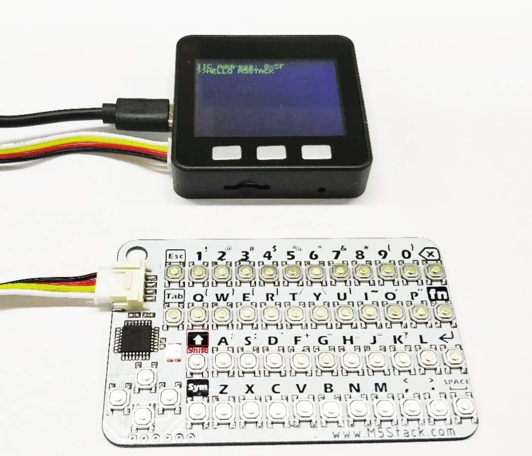
Figure 2.2 — Cardputer QWERTY keyboard. Photo via web image search.
The keyboard is soft-membrane (rubber-dome-style under a soft cover), driven by a TI TCA8418RTWR I²C keyboard scanner. Matrix layout: 4 rows × 14 columns = 56 keys.
Table 3 — 4. Keyboard — TCA8418RTWR scan matrix
| Parameter | Value | Notes |
|---|---|---|
| Scanner IC | TI TCA8418RTWR | I²C address typically 0x34 |
| Matrix | 4 rows × 14 cols → 56 keys | Some positions are modifier keys (Fn, Ctrl, Alt, Shift, OK) |
| Actuation force | ~160 gf | Soft membrane — comfortable for typing, not for fast-finger games |
| Polling | Event FIFO on the TCA8418, read by ESP32-S3 via I²C interrupt (G11) | Polling rate ~50 Hz from the host side |
| Key rollover | 2-key rollover typical | The TCA8418 supports 4-key rollover; firmware-side limit |
| Auto-repeat | Configurable per build (M5Cardputer library has a setting) | Default ~250 ms initial delay + ~50 ms repeat rate |
Modifier-key behavior: Fn unlocks the secondary layer (function keys, brightness/volume keys, symbols). Ctrl + Alt + Shift behave like a standard PC keyboard. OK key behaves like Enter.
Layout: standard 14-column QWERTY arrangement with a 4-row form factor. Some keys consolidate two physical letters (e.g., one key for both a number and a symbol via Fn). Specific layout chart: see Cardputer ADV vendor docs (the layout PDF is the authoritative reference).
TCA8418 quirks worth knowing:
- The chip maintains an event FIFO. If the host doesn’t drain it, keystrokes back up — but on key-down + key-up events, not on a per-character basis. Worst case ~64 events queued before drops.
- The chip can generate an interrupt on G11 when events are pending. M5Cardputer library wires this; bare-metal code should too.
- Boot-time initialization: the TCA8418 needs ~10 ms after I²C-config-write before it starts scanning. Splash-screen during boot covers this.
2.5 Audio chain — ES8311 + NS4150B + MEMS mic + 3.5 mm jack
The audio subsystem is the most-complete part of the Cardputer ADV. Chain:
   MEMS mic  ──┐
               ├── ES8311 codec ──┬── NS4150B amp ── speaker
   3.5 mm in ──┘                  └── 3.5 mm headphone out
                  (I²S audio + I²C control)
Table 4 — 5. Audio chain — ES8311 + NS4150B + MEMS mic + 3.5 mm jack
| Component | Part | Function |
|---|---|---|
| Codec | Everest ES8311 | I²C config + I²S audio bus. 24-bit, up to 96 kHz sample rate. Mic preamp + output mixer + headphone driver. |
| Amplifier | NS4150B | 1 W class-D amp driving the on-board speaker. PD pin tied so the amp can be muted. |
| Microphone | MEMS (omnidirectional) | Bottom-firing. SNR ~65 dB. Used for: voice recording, FFT analyzer, ESP-NOW walkie-talkie. |
| Headphone jack | 3.5 mm TRRS | TRRS = Tip-Ring-Ring-Sleeve (4-conductor; supports headset with mic). Auto-mutes on-board speaker on insertion via a mechanical switch contact. |
Sample-rate ceilings:
- 96 kHz / 24-bit possible but heap-heavy. Mainline firmwares use 16 kHz / 16-bit or 22.05 kHz / 16-bit for most use cases.
- Wake-word detection (esp-skainet) typically runs at 16 kHz.
- Internet radio (RHesus-RAdio) runs at the bitrate of the streamed source (commonly 128 kbps MP3 at 44.1 kHz).
Audio applications shipping for Cardputer ADV:
- Voice memo recorder (MEMS mic → SD)
- Internet radio receiver (Wi-Fi → ES8311 → speaker/jack)
- FFT audio spectrum (mic → real-time 16-band bar graph)
- ESP-NOW walkie-talkie (push-to-talk over Wi-Fi raw frames, Vol 9 § 5)
- Audio FX / DAW prototyping (very low-end; CPU-bound)
Note on output power: NS4150B is rated 1 W into 8 Ω. The on-board speaker is small; sounds adequate in a quiet room, drowned out in noisy environments. 3.5 mm headphone output is the better path for serious listening.
2.6 IMU — BMI270 6-axis
The Bosch BMI270 is a 6-axis IMU (3-axis accelerometer + 3-axis gyroscope) on the shared I²C bus.
Table 5 — 6. IMU — BMI270 6-axis
| Parameter | Value | Notes |
|---|---|---|
| Accel range | ±2 / ±4 / ±8 / ±16 g | Configurable per use case |
| Gyro range | ±125 / ±250 / ±500 / ±1000 / ±2000 °/s | Same |
| Output rate | up to 6.4 kHz | Mainline firmwares typically run at 100-200 Hz |
| Interface | I²C | Address 0x68 (alternate 0x69 — varies by board) |
| Built-in features | Step counting, gesture recognition (single/double tap, flat/no-flat, significant-motion) | Bosch’s BSX algorithms run on-chip; results delivered via interrupt |
| Power | ~120 µA continuous accel, ~850 µA continuous gyro | Negligible vs display backlight |
Use cases enabled by the BMI270:
- Shake-to-snooze — Pomodoro timer module (Vol 9 § 6) listens for “any motion” interrupt
- Screen rotation — autorotate display based on orientation
- POV LED art — accelerometer + RGB LED + integrated position estimate to draw messages in air (Vol 9 § 6)
- Step counting — for fitness / activity logging
- Tamagotchi-style pet interaction — raising-hell-cardputer uses shake-to-feed
The BMI270 ships well-supported by BMI270_Arduino library and is integrated into the M5Unified library so most application code can ignore the low-level details.
2.7 IR transmit — 940 nm on GPIO44
The Cardputer ADV has a single 940 nm IR LED on GPIO 44 for IR transmission. No on-board IR receiver — for IR learning (capturing remote codes), pair with a Grove IR Unit that has RX.
Table 6 — 7. IR transmit — 940 nm on GPIO44
| Parameter | Value | Notes |
|---|---|---|
| LED wavelength | 940 nm | Standard for consumer-electronics remotes (TVs, ACs, audio receivers) |
| Drive pin | GPIO 44 | Direct ESP32-S3 GPIO; modulated by firmware |
| Power | ~50 mA peak during TX bursts | Within ESP32-S3 GPIO drive capability (~40 mA continuous, peaks higher OK) |
| Range | ~3-5 m direct line-of-sight | Comparable to consumer TV remotes |
| Modulation | NEC, RC5, RC6, Sony, manufacturer-specific | Bruce + NEMO + M5CardRemote ship extensive code databases |
IR applications:
- TV-B-Gone (Bruce, NEMO) — flood common TV-off codes; turns off most TVs in proximity. Crowd-pleaser at parties; obnoxious at parties.
- AC-B-Gone — same concept for AC units
- Custom replay — record (via Grove IR Unit RX) + send (via on-board TX)
- Universal remote — M5CardRemote ships hundreds of codes organized by device type
2.8 microSD slot + SPI bus sharing
The microSD slot is on the side. The card is accessed via SPI mode (not the higher-speed SDIO 1-bit or 4-bit modes — those require more GPIOs than the Cardputer ADV routes).
Table 7 — 8. microSD slot + SPI bus sharing
| Parameter | Value | Notes |
|---|---|---|
| Interface | SPI mode (1-bit) | Up to ~25 MHz SPI clock; ESP32-S3 driver typically runs at 4-20 MHz |
| Max card size | exFAT to 1 TB, FAT32 to 32 GB native | Larger FAT32 needs explicit host-side formatting |
| Recommended | 8-32 GB Class 10 / U1 | Sweet spot — adequate for OTA, captures, retro ROMs |
| Filesystem | FAT32 (preferred) or exFAT | Arduino-ESP32 SD.h supports both |
| CS pin | GPIO 12 | Vol 3 § 2 carries the full pin table |
The shared-SPI-bus issue:
The microSD shares the SPI bus with the display (TFT) and with any EXT-bus SPI peripheral (Cap LoRa-1262 SX1262). Three peripherals on one bus, three different chip-select lines (display CS = on Stamp-S3A internal, SD CS = G12, EXT CS = G5).
Implications:
- Long SD writes block display refresh for the duration of the write. Visible as a brief “freeze” on screen during large file writes.
- Concurrent SD + LoRa SPI operations are serialized through the bus arbiter. M5Cardputer + RadioLib + SD.h handle the arbitration but contention reduces effective throughput on each.
- For high-throughput capture (e.g., probe-request flooding into a pcap), pre-allocate a RAM buffer and flush to SD periodically rather than per-packet.
2.9 Power subsystem — 1750 mAh LiPo + SY8089 buck + charge quirks
The power tree:
   USB-C ──┬── (side switch) ── charge controller ── LiPo +─┐
           │                                                 │
           │                                                 ↓
           └──────────── battery sense (G10 ADC) ─── SY8089 buck ── 3.3 V rail
                                                              │
                                                              └─── 5 V boost (separate, for Grove 5V output)
Table 8 — 9. Power subsystem — 1750 mAh LiPo + SY8089 buck + charge quirks
| Parameter | Value | Notes |
|---|---|---|
| Battery | 1750 mAh single-cell LiPo, ~3.7 V nominal | JST-PH 2-pin connector internally |
| Buck converter | SY8089 | Battery (3.0-4.2 V) → 3.3 V system rail |
| Charge controller | Standard TP4056-class IC | Charge current ~500 mA |
| Side switch | Mechanical SPST on the side | Must be ON for USB charging to work |
| Charge time | ~4 hours from empty to full | At 500 mA charge current |
| Battery telemetry | G10 ADC via voltage divider (~0.49× V_BAT) | Wrong calibration shows 47% as 95% — known firmware-author footgun |
Current-draw measurements (vendor specs + community confirmation):
Table 9 — Current-draw measurements (vendor specs + community confirmation)
| Mode | Current | Notes |
|---|---|---|
| Idle (display backlight + scan loop) | ~120 mA | Backlight dominates |
| Wi-Fi station active | +12 mA | Radio in RX/TX-occasional |
| BLE peripheral active | +35 mA | BLE radio |
| Display backlight off (sleep variant) | ~30 mA | Most apps don’t reach this state |
| Sustained Wi-Fi TX (deauth spam) | +130-280 mA peak | Brownout territory on weak batteries |
| Cap LoRa-1262 TX +22 dBm | +163 mA peak | SX1262 datasheet number |
| Deep sleep (mainline firmwares don’t use) | 0.23 µA | Theoretical; opt-in for custom code |
Battery-life estimates (1750 mAh stock):
- Idle / menu navigation: ~14 hours
- Wi-Fi scan continuous: ~10 hours
- Sustained TX-spam attacks: ~3-5 hours
- Meshtastic LongFast with GPS + Wi-Fi off: ~24 hours
- Solar-harvested static deployment: indefinite (with appropriate panel — Vol 9 § 3.3)
The charging quirk (most-asked-about):
The side switch must be ON for USB-C charging to work. When the switch is OFF, USB-C is electrically disconnected from the charge controller — the device acts as if no USB power is present. This is by design (the switch is a true power-disconnect, not just a soft button). New users routinely wonder “I plugged it in but it’s not charging” — the answer is almost always “side switch is OFF.”
USB enumeration (for firmware flashing / serial console) works regardless of switch position because that path runs directly through the ESP32-S3’s native USB peripheral, not through the charge controller.
Brownout posture (covered in detail in Vol 11 § 5):
ESP32-S3 has a brownout detector that trips at ~2.7 V (configurable). Under sustained TX-spam with a weak battery, the supply rail dips → SoC resets → attack appears to “stop working” but actually the device rebooted. Symptoms: visible reboot animation mid-attack, or attack menu returns to the launcher unexpectedly.
Mitigations: fresh / larger battery; known-good USB cable for USB-powered operation; avoid concurrent SD writes during TX-heavy attacks; or rebuild firmware with CONFIG_ESP_BROWNOUT_DET_LVL_SEL_5 (less aggressive threshold) — see Vol 10 § 10.
2.10 Mechanical — enclosure, magnets, LEGO-Technic, lanyard
Table 10 — 10. Mechanical — enclosure, magnets, LEGO-Technic, lanyard
| Parameter | Value |
|---|---|
| Dimensions | 84 × 54 × 19.6 mm |
| Weight | 81 g |
| Material | Polycarbonate-ABS blend, glass-fiber-reinforced |
| Back surface | Neodymium magnets (4× 6×2 mm typical) — sticks to ferrous metal |
| Base | LEGO-Technic-compatible mounting holes |
| Top edge | Lanyard hole |
The magnetic back is the underrated feature. The Cardputer ADV sticks to refrigerators, file cabinets, server racks, metal locker doors. Combined with a long battery life this enables “stick it to the side of the rack and walk away” deployments — Wi-Fi monitor, Meshtastic relay, etc.
LEGO Technic compatibility matters for custom rigs — print or 3D-print a holder, mount the Cardputer ADV via Technic pins, attach to drones / toy vehicles / camera tripods / wearable straps. Community 3D-printable holders are on Thingiverse and Printables.
Lanyard hole: useful for conference wear / drop protection. M5Stack sells a lanyard accessory but any 3 mm-cord lanyard fits.
2.11 Per-subsystem BOM highlights
Authoritative parts identified from vendor docs + teardowns:
Table 11 — Authoritative parts identified from vendor docs + teardowns
| Subsystem | Component | Vendor | Datasheet |
|---|---|---|---|
| MCU module | Stamp-S3A | M5Stack | M5Stack docs |
| MCU chip | ESP32-S3FN8 | Espressif | https://www.espressif.com/sites/default/files/documentation/esp32-s3_datasheet_en.pdf |
| Display | ST7789V2 controller + 1.14″ IPS panel | Sitronix (controller) | Sitronix ST7789V2 |
| Keyboard scanner | TCA8418RTWR | TI | https://www.ti.com/product/TCA8418 |
| Audio codec | ES8311 | Everest | https://www.everest-semi.com/ |
| Audio amp | NS4150B | Various (commodity class-D) | NS4150B datasheet |
| IMU | BMI270 | Bosch | https://www.bosch-sensortec.com/products/motion-sensors/imus/bmi270/ |
| IR LED | 940 nm SMD IR LED | Generic | n/a |
| Buck converter | SY8089 | Silergy | SY8089 datasheet |
| Charge controller | TP4056 family | NanJing Top Power | TP4056 datasheet |
| Battery | 1750 mAh single-cell LiPo | M5Stack-sourced | n/a (vendor-specific) |
For replacement parts: battery is the most-replaced (LiPos age out at 300-500 cycles). 3000 mAh upgrade via parallel-stack covered in Vol 9 § 4.1.
2.12 What isn’t on board (and where to find it)
Re-statement of capability gaps from Vol 1 § 4.2 with hardware emphasis:
Table 12 — Re-statement of capability gaps from [Vol 1 § 4.2](/m5stack-cardputer-adv/deep-dive/vol-1/#142-what-it-cannot-do-even-with-the-lora-cap) with hardware emphasis
| Missing | Workaround |
|---|---|
| 5 GHz Wi-Fi | M5MonsterC5 (Grove-port ESP32-C5 coprocessor, Vol 4 § 5) |
| PSRAM | No workaround — different ESP32-S3 SKU required (FN16 etc.). Affects buffer sizes only. |
| NFC controller | Unit RFID2 (WS1850S Grove) or PN532 Grove I²C |
| Camera | None — different M5Stack product needed (Atom S3R / Core S3) |
| Cellular modem | NB-IoT / 4G LTE / Cat-M Grove Units |
| Ethernet PHY | ATOM PoE or W5500 Grove Unit |
| HF GNSS (RTK) | None on-board; Atomic GPS Kit (NEO-M8N) Grove for slightly better than the Cap’s AT6668; full RTK requires dedicated module not in M5 ecosystem |
| Sub-GHz CC1101 | CC1101 Grove Unit or wired to EXT bus when Cap LoRa-1262 is removed (Vol 4 § 6.2) |
| 433 MHz LoRa native | Re-antenna the Cap LoRa-1262 + matching network, OR add 433 MHz Tx+Rx Grove Units |
| BT classic | None — different ESP32 silicon required (ESP32-WROOM-32 classic). Affects only legacy BT-classic devices |
| Camera bus / DVP / MIPI-CSI | Not exposed on Cardputer ADV |
| Hardware random / TRNG separate from on-SoC | ESP32-S3’s on-SoC TRNG is the only option |
The Cardputer ADV is a Wi-Fi/BLE/LoRa/IR/audio platform — outside that envelope, sister Hack Tools projects cover the gaps (Flipper for full sub-GHz library, Proxmark3 for NFC depth, HackRF for SDR breadth, Wi-Fi Pineapple for Wi-Fi 6).
2.13 Resources
Datasheets
- ESP32-S3: https://www.espressif.com/sites/default/files/documentation/esp32-s3_datasheet_en.pdf
- ST7789V2: Sitronix
- TCA8418 keyboard scanner: https://www.ti.com/product/TCA8418
- ES8311 codec: https://www.everest-semi.com/
- BMI270 IMU: https://www.bosch-sensortec.com/products/motion-sensors/imus/bmi270/
- SY8089 buck: Silergy
- TP4056 charge IC: NanJing Top Power
Vendor
- Cardputer ADV docs: https://docs.m5stack.com/en/core/Cardputer
- Stamp-S3A module: https://shop.m5stack.com/products/m5stamps3
- Cardputer-Adv Structure Files PDF: https://docs.m5stack.com/
Libraries
- M5Cardputer Arduino library: https://github.com/m5stack/M5Cardputer
- M5Unified library: https://github.com/m5stack/M5Unified
- M5GFX library: https://github.com/m5stack/M5GFX
Forward references in this series
- Pinout + expansion buses (the per-pin interface): Vol 3
- Module ecosystem (what plugs in): Vol 4
- Cap LoRa-1262 + GNSS (the radio companion): Vol 5
- Firmware that runs on this hardware: Vol 6
- Power profile + brownout details: Vol 11 § 5
This is Volume 2 of a twelve-volume series. Next: Vol 3 walks the per-pin pinout and the expansion buses — Grove HY2.0-4P, the 14-pin EXT bus, and USB-C OTG.
Comments (0)