Ruckus Game Over · Volume 2
Game Over Module — Volume 2
Hardware Reference
Schematic-grade walk-through of the Game Over module. This volume covers what’s actually on the board, why the architecture choices matter, and what you need to know to either operate it confidently or open it up and modify it.
The vendor does not publish a schematic. The information here is compiled from:
- The Tindie product page (vendor primary source — explicit BOM claims, the expansion-slot pin-out, antenna requirements).
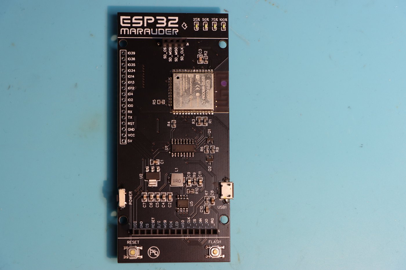
- Photos and reviews of actual units (form factor, indicators, port layout).
- Marauder firmware source (which hardware initialization tells us about pin assignments — see Vol 3 for how to read it).
- Direct comparison with the Flipper Devices WiFi Devboard reference design (which shares the UART-bridge convention and 8-pin daughter- slot pin-out family).
Where I’m uncertain or extrapolating, I flag it explicitly. This is a hardware reference, not a wishful-thinking document.
2.1 Block diagram (architectural)
            ┌──────────────────────────────────────────┐
            │             Game Over Module             │
            │                                          │
SMA-1 ──────┤  ESP32-S3 ── 2.4 GHz Wi-Fi/BLE PA/LNA    │
            │     │                                    │
            │     │ SPI to ─────────┐                  │
            │     │ daughter slot   │                  │
            │     │                 │                  │
            │     ├── I²C ── SSD1306 OLED (128×64)     │
            │     ├── GPIO ─ Joystick (UP/DOWN/PUSH)   │
            │     ├── GPIO ─ RGB status LED            │
            │     ├── GPIO ─ RX/TX activity LEDs       │
            │     ├── GPIO ─ BOOT / RESET buttons      │
            │     ├── SPI ── microSD slot              │
            │     └── UART ── (to Flipper via header)  │
            │                                          │
            │  ┌────────────┐                          │
            │  │  Daughter  │                          │
SMA-2 ──────┤  │   Slot     ├──── (CC1101 or NRF24,    │
            │  │  (8-pin)   │      mutually exclusive) │
            │  └────────────┘                          │
            │                                          │
            └──────────┬───────────────────────────────┘
                       │
        ┌──────────────┼─────────────────────┐
        │  18-pin GPIO header  ─── Flipper   │
        │  (3V3, GND, UART, control GPIOs)   │
        └────────────────────────────────────┘
Key architectural traits:
- Single MCU — the ESP32-S3 is the entire compute. Unlike AWOK Dual Touch (which has two parallel ESP32s), Game Over is a single-radio board with a daughter-slot expansion path.
- The daughter slot is a peripheral SPI bus, not a parallel radio. Whichever daughter card is installed is operated by the ESP32-S3 over SPI, exactly the same protocol the Flipper uses for its onboard CC1101.
- Antenna paths are physically independent — one SMA for the ESP32-S3 (2.4 GHz), one SMA on the daughter card (sub-GHz for CC1101, 2.4 GHz for NRF24). They are not combined or diversity-switched.
- Power for everything is sourced from either USB-C (if you connect one — the vendor’s exact USB-C topology varies; some Game Over batches have USB-C on the module, others rely on the Flipper rail) or the Flipper 3V3 rail through the GPIO header. Power topology is the single biggest reliability question on this board — see Vol 7.
2.2 The ESP32-S3 (host MCU)
2.2.1 Why ESP32-S3 specifically
The ESP32-S3 was the right MCU choice for a multi-radio Flipper add-on in 2023–24 when Game Over was designed:
- 2.4 GHz Wi-Fi (b/g/n) + BLE 5.0 built in.
- USB OTG (full-speed USB controller in silicon) — letting the board enumerate as a USB device directly without a separate UART bridge. Useful for the dirty_flasher path (Vol 3) and for HID injection experiments.
- Dual Xtensa LX7 cores @ 240 MHz, 512 KB SRAM, 384 KB ROM, plus external PSRAM via QSPI on most ESP32-S3 modules.
- More GPIO than ESP32-S2 (45 vs 22 usable pins), which is what makes
driving an OLED + joystick + daughter-slot SPI + microSD + LEDs + UART
- buttons all feasible from a single chip.
- Marauder upstream supports it natively — which the vendor’s fork inherits. (Vol 3 has the Marauder-side implications.)
By contrast:
Table 1 — By contrast
| MCU | Why not | When you’d see it |
|---|---|---|
| ESP32-S2 (WROVER) | No BLE silicon; less GPIO | Flipper Devices WiFi Devboard |
| ESP32-WROOM-32 | Older silicon, less GPIO, no USB-OTG | AWOK Dual Touch V3 (× 2) |
| ESP32-C3 | Smaller — too few GPIOs for this BOM | Apex 5 uses C5 (newer) instead |
| ESP32-C5 | Newer (5 GHz Wi-Fi 6) but post-dates Game Over | Apex 5 |
The ESP32-S3 is on its way out for new designs (the C5 with 5 GHz support is the current state-of-the-art for Flipper Wi-Fi work), but for Game Over’s mission it’s still well-suited.
2.2.2 ESP32-S3 module variant — the unknown
The vendor doesn’t publish which specific ESP32-S3 module is fitted. The two most common variants:
- ESP32-S3-WROOM-1 — 4 MB or 8 MB internal flash, no PSRAM
- ESP32-S3-WROOM-1U — variant with u.FL antenna connector instead of PCB trace
- ESP32-S3-WROVER — adds 2 MB or 8 MB PSRAM
Game Over has an SMA antenna jack for the ESP, which means the chip’s internal antenna is bypassed (or the module is the -1U variant with u.FL). The vendor’s photos show what looks like the standard WROOM-1 metal can with an external coax to SMA, but verify on hardware.
Why this matters: memory budget. The Marauder firmware fork that
ships pre-loaded fits comfortably in 4 MB. Custom firmware that wants to
include large captive-portal HTML libraries, or a multi-protocol decoder,
or LVGL, may bump up against an 8 MB partition table limit if the module
is 4 MB. Plan to run esptool.py flash_id once you have the unit to
confirm.
2.2.3 Pin assignments (extrapolated from Marauder source + vendor pinout)
The Marauder fork’s hardware-init code is the authoritative document for
pin assignments. Reading the upstream
configs/marauder_dev_board_pro.h-style configs (which the vendor’s fork
broadly mirrors), the relevant pins for Game Over are approximately:
Table 2 — broadly mirrors), the relevant pins for Game Over are approximately
| Function | ESP32-S3 GPIO | Notes |
|---|---|---|
| OLED I²C SDA | GPIO 38 (typical) | Verify on Marauder source for exact value |
| OLED I²C SCL | GPIO 37 (typical) | |
| Joystick UP | GPIO ~13 | Active-low with internal pull-up |
| Joystick DOWN | GPIO ~14 | |
| Joystick PUSH | GPIO ~15 | |
| Daughter slot SPI MOSI | GPIO ~11 (Marauder dev board pro) | A6 in vendor pinout terms |
| Daughter slot SPI MISO | GPIO ~12 | A7 |
| Daughter slot SPI SCK | GPIO ~10 | B3 |
| Daughter slot CS | GPIO ~9 | A4 |
| Daughter slot GD0/IRQ | GPIO ~17 | 1W |
| Daughter slot reset | GPIO ~16 | B2 |
| microSD SPI | shared with daughter slot | Conflict — see § 5.3 |
| Flipper UART TX | GPIO ~43 (S3 default UART) | |
| Flipper UART RX | GPIO ~44 |
Caveat. These pin numbers are inferred from the Marauder Dev Board Pro reference and the typical S3 → S3 mapping. The Game Over fork may differ. For authoritative pin assignments, read the Marauder fork binary or ask the vendor directly. Pinning matters when you’re writing custom firmware (Vol 3 § 6); it doesn’t matter when you’re just running the stock binary.
2.3 The OLED + Joystick UI (the standalone-mode killer feature)
2.3.1 The display
- Controller: SSD1306 (or SH1106 — both are pin- and protocol- compatible at the I²C level for typical drivers).
- Resolution: 128 × 64 monochrome.
- Connection: I²C, address 0x3C (default for SSD1306-class panels).
- Vendor description: “Power efficient OLED screen.”
This is a small display — significantly smaller than the Flipper’s own 128 × 64 LCD or the AWOK’s 320 × 240 touchscreen. Marauder’s UI is designed for it (compact menus, scrolling lists, single-line status text). Custom firmware should plan for the same constraint.
2.3.2 The joystick
A 3-way joystick — UP, DOWN, and PUSH (center click). No left/right.
This is unusual but workable. Marauder’s UI is:
- UP / DOWN to navigate menu items.
- PUSH to select.
- “Back” is implemented as a long-press of PUSH or as the top item of every submenu.
The constraint is real. If you’re writing custom firmware (Vol 3 § 6), budget UI complexity around three inputs rather than five.
2.3.3 LEDs
Three categories of LED on the board:
- RGB status indicator — driven from the ESP32-S3 (likely on a GPIO + WS2812 or three-pin RGB LED). Marauder uses it for attack/ sniffing status (idle, scanning, attacking, packet captured).
- RX/TX activity LEDs — typical USB-UART activity indicators on the Flipper-bridge UART path. They blink when traffic is moving between the ESP32-S3 and the Flipper.
- Power LED — single-color, indicates board powered.
The RGB LED is the user-facing one; the others are diagnostic.
2.3.4 Buttons
Two buttons:
- BOOT — pulls GPIO 0 to ground when held during reset, dropping the ESP32-S3 into ROM bootloader mode for flashing (Vol 4 § 3).
- RESET — drives the EN line low briefly. Same as a power cycle.
Standard Espressif convention. Same as on every ESP32 dev board.
2.4 The daughter-card expansion slot
This is the slot that turns Game Over from “a screen for Marauder” into “a configurable multi-radio platform.”
2.4.1 Vendor-provided pin-out
From the Tindie page (canonical):
  ┌─────────────┬─────────────┐
  │ 1: GND      │ 2: 3V3      │
  ├─────────────┼─────────────┤
  │ 3: B2       │ 4: A4       │
  ├─────────────┼─────────────┤
  │ 5: B3       │ 6: A7       │
  ├─────────────┼─────────────┤
  │ 7: A6       │ 8: 1W       │
  └─────────────┴─────────────┘
The pin labels (A4, A6, A7, B2, B3, 1W) are Flipper-domain
net names — they correspond to Flipper Zero GPIO net naming, not ESP
GPIO numbers. This is a tell that the slot was designed to mirror the
Flipper Devices WiFi Devboard / Marauder Dev Board convention,
where the same daughter cards meant for those reference boards plug
directly into Game Over.
Mapping to function (matching the standard Marauder devboard family):
Table 3 — Mapping to function (matching the standard Marauder devboard family)
| Pin | Net name | Function for CC1101 daughter | Function for NRF24 daughter |
|---|---|---|---|
| 1 | GND | Ground | Ground |
| 2 | 3V3 | Power (3.3 V) | Power (3.3 V) |
| 3 | B2 | Reset (active low) | Reset / CE |
| 4 | A4 | CS (chip select, active low) | CSN |
| 5 | B3 | SCK | SCK |
| 6 | A7 | MOSI | MOSI |
| 7 | A6 | MISO | MISO |
| 8 | 1W | GDO0 (general digital output 0 — packet-status / IRQ) | IRQ |
In CC1101 terms: GDO0 is the wake-on-packet / RX-FIFO-threshold output that the Marauder code uses to know when a packet arrived. In NRF24 terms: IRQ is the same conceptual signal.
2.4.2 Mechanical
The slot is described as recessed and reinforced — meaning the daughter card sits flush within the case rather than projecting above it, and the connector is a robust 2 × 4 header rather than a fragile edge connector.
The vendor explicitly says: “recessed reinforced expansion module header (nice snug fit for CC1101 or NRF24).”
The slot is not keyed. It’s the user’s responsibility to insert the daughter card correctly. Vol 7 § 3 covers the orientation hazard (reverse-insertion can kill an NRF24 daughter card; CC1101 is generally more tolerant but not bulletproof).
2.4.3 SPI bus sharing
The daughter slot’s SPI lines (B3 = SCK, A7 = MOSI, A6 = MISO) are shared with the microSD card SPI bus — both peripherals are slaves on the same bus, with separate chip-select lines.
This is normal for ESP32 boards but worth knowing because:
- You can’t read/write SD and operate the daughter card simultaneously on the same SPI transaction. The Marauder firmware handles this (sequential access), but custom firmware needs to as well.
- High SPI clock rates that work for one peripheral may not work for the other. SD cards generally tolerate up to 25 MHz; CC1101 maxes at ~10 MHz; NRF24 at 8 MHz. Marauder runs the bus at ~5 MHz to be safe.
2.4.4 Compatible daughter cards
Per the vendor’s page:
Any module that uses the following pin-out is compatible, currently tested & confirmed modules: CC1101 & NRF24.
In practice this means:
- CC1101 daughter cards sold by JustCallMeKoko (Marauder dev board family), rg4geek, and others targeting the Flipper / Marauder ecosystem are pin-compatible.
- NRF24L01+ daughter cards sold by JustCallMeKoko, YIHANG, and others are pin-compatible.
- Sub-GHz daughter cards intended for other footprints (e.g. Mayhem v2’s mutually-exclusive slot) may look the same but use different pinning. Don’t assume — check the seller’s documentation.
The recessed header keys against the daughter card body, but it doesn’t guarantee electrical compatibility. Check the daughter card’s silk for “Marauder dev board pro” or “Flipper compatible” labels before buying.
2.5 The microSD subsystem
2.5.1 Physical
- Slot: standard push-push microSD on the side of the board.
- Bus: SPI, shared with the daughter slot (§ 5.3).
- Card support: vendor explicitly recommends Lexar and Kingston brands. Sandisk cards have known compatibility issues — see Vol 7 § 2.
The vendor’s response to a Sept 2024 review made the SD-card situation concrete:
There is a known issue with newer Sandisk branded microSD’s, this is an upstream espressif API issue and not related to the board at all. It should eventually be fixed. Some Sandisk cards work fine, others fail to mount. Lexar & Kingston branded microSD’s are known working cards, I recommend using these.
2.5.2 What gets written
Marauder uses the SD card for:
- PCAP files of sniffed Wi-Fi traffic (the headline feature).
- WiGLE-format wardriving logs when GPS is connected (note: Game Over has no internal GPS, so this requires an external feed — see Vol 6 § 5).
- Captured probe-request lists, beacon scans, etc.
- Captive portal HTML files (Evil Portal feature) for runtime-loadable attack pages.
A 32 GB or 64 GB card is plenty; Marauder writes are slow-and-steady, not high-throughput.
2.5.3 SD-card vs Flipper-SD
When the Game Over is mounted on a Flipper, two SD cards are present in the system: Game Over’s onboard SD and the Flipper’s SD. They are independent. Marauder writes to the Game Over SD. The Flipper’s SD is used only for the Flipper’s own files (FAPs, sub-GHz captures, etc.), unless you configure the Marauder companion FAP to also log to the Flipper SD as a backup.
2.6 Antennas
2.6.1 The two SMA jacks
- SMA-1: the ESP32-S3 antenna path — 2.4 GHz Wi-Fi/BLE.
- SMA-2: the daughter card antenna path — 433/868/915 MHz for CC1101, 2.4 GHz for NRF24.
Both are full-size SMA, not RP-SMA. Standard 2.4 GHz “rubber duck” Wi-Fi antennas (which are usually RP-SMA in consumer products) will not fit without an adapter. Use SMA-male antennas designed for SDR / ham radio dev work.
2.6.2 Antenna ground sharing (the gotcha)
The CC1101 daughter-card antenna ground and the Flipper’s onboard CC1101 antenna ground are electrically tied through the GPIO header’s GND pins.
Practical consequence: don’t transmit on both Game Over’s CC1101 daughter and the Flipper’s onboard CC1101 simultaneously. The shared ground can backfeed RF energy and damage one or both PA stages. Vol 7 § 4 covers the exact symptoms and mitigation.
This is an artifact of the Flipper’s hardware design (single GND across the GPIO header); it’s not specific to Game Over and would apply to any sub-GHz daughter board. But Game Over is the most common case to hit it.
2.6.3 Vendor warning (worth repeating)
Do not run any modules without an antenna attached, as you will damage them.
This applies most stringently to the daughter card (CC1101 or NRF24). The PA stage on a CC1101 is unprotected against open-circuit reflection at full TX power; a single 1-W transmit burst into an open SMA jack can cook it. Always have the antenna installed before powering on.
2.7 Power architecture
This is the section that matters most for the “alleged Flipper-bricking” issue investigated in Vol 7.
2.7.1 Where power comes in
Two paths:
- From the Flipper 3V3 rail through the GPIO header (when mounted on a Flipper, no separate USB-C connected to Game Over).
- From an external USB-C on the Game Over itself, when one is present and connected.
The vendor’s product description is unclear on whether all Game Over batches have an onboard USB-C or only some. The YouTube product walkthroughs show a USB-C port on the side of recent units. Verify on your own unit; if it’s there, use it for any session that involves sustained Wi-Fi attack work (deauth bursts, evil portal serving over SoftAP, etc.). Powering the board off the Flipper rail alone is the documented cause of brownouts.
2.7.2 The 3V3 budget reality
The Flipper’s 3V3 GPIO rail is community-rated ~150 mA continuous across all GPIO loads. The Flipper can briefly source more, but sustained draw above 150 mA risks brownouts of the Flipper’s own subsystems.
Game Over’s draw, observed and estimated:
Table 4 — Game Over's draw, observed and estimated
| State | Approx. current |
|---|---|
| Idle (OLED on, ESP-S3 deep sleep, no daughter) | 30–50 mA |
| Idle + Marauder UI active | 70–100 mA |
| Wi-Fi scan (ESP-S3 RX active) | 120–180 mA |
| Wi-Fi deauth burst (ESP-S3 TX) | 200–350 mA peaks |
| Sub-GHz TX via CC1101 daughter | +50–150 mA on top |
| BLE spam (ESP-S3 TX bursts) | 250–400 mA peaks |
Read that table carefully. Most active-attack states exceed the Flipper 3V3 continuous budget. The Flipper handles it by browning out its own peripherals first (BLE drops, sub-GHz radio resets). In some cases — and this is the bricking story — the brownout is severe enough to corrupt Flipper firmware state or damage the Flipper’s PMIC.
2.7.3 The vendor’s mitigation history
From the review timeline:
- Pre-2024 / early 2024 batches had the worst over-current behavior. Reviews from that era include accounts of bricked Flippers.
- Mid-2024 vendor pushed firmware updates that throttled TX power and added current limiting in software.
- 2025 firmware iterations further reduced the brownout risk.
- Feb 2026 review still reports two damaged Flippers — meaning the issue is not fully resolved, even on current units, when operated without external USB-C power on the module.
The practical rule: always power Game Over via its own USB-C during attack work. Use the Flipper rail only for passive scanning / OLED-only operation.
2.7.4 The wider lesson
This is not unique to Game Over. Multi-radio Flipper daughter boards in general (Game Over, Mayhem v2, FlipMods, Apex 5, Rek5) all draw more than the 3V3 budget under attack loads. The Flipper’s GPIO header was designed for sensors and simple peripherals; it’s weak as a platform- power source for a 1-W RF transmitter.
Apex 5 explicitly ships with a USB-C and warns about Flipper-only operation. Mayhem v2 has the same warning. Game Over’s marketing is less explicit, which is why the bricking allegations attach to it more often.
2.8 The 18-pin GPIO header (Flipper-facing)
Game Over connects to the Flipper through the standard 18-pin GPIO header. The relevant pins:
Table 5 — header. The relevant pins
| Flipper pin | Function | Game Over use |
|---|---|---|
| 1 | +5V (USB-derived) | Not used by Game Over |
| 8 | +3V3 (Flipper rail) | Powers Game Over when no USB-C |
| 9, 11, 18 | GND | Ground |
| 13 (UART TX) | UART to Game Over | Flipper sends Marauder commands |
| 14 (UART RX) | UART from Game Over | Game Over sends results / status |
| 15, 16 (I²C) | Not used | Reserved |
| 17 (RX) | Boot-control during flash | dirty_flasher uses this for ESP32-S3 BOOT signal |
| 7 (TX) | Boot-control during flash | dirty_flasher uses this for ESP32-S3 RESET signal |
| Others | Available | Not used by stock firmware |
The flash-via-Flipper path (Vol 4 § 4) leverages pins 7 and 17 to
toggle the ESP32-S3’s BOOT/RESET lines, putting it into ROM bootloader
mode without requiring physical button presses. This is the path
dirty_flasher uses when invoked from the Marauder companion FAP.
2.9 Capability matrix vs board-level ceiling
Table 6 — 10. Capability matrix vs board-level ceiling
| Capability | Possible on Game Over? | Notes |
|---|---|---|
| 2.4 GHz Wi-Fi b/g/n scanning | Yes | ESP32-S3 native |
| 2.4 GHz Wi-Fi deauth (firmware-permitting) | Yes | Marauder fork ships it |
| Evil Portal / captive-portal phishing | Yes | Marauder feature |
| BLE 5.0 scanning + advertising + spam | Yes | ESP32-S3 native |
| 5 GHz Wi-Fi | No | Hardware doesn’t have it (S3 = 2.4 GHz only) |
| Sub-GHz (433/868/915 MHz) | Yes, via CC1101 daughter | Daughter card required |
| 2.4 GHz NRF24 mousejacking | Yes, via NRF24 daughter | Daughter card required |
| LoRa | No | No SX1262/76 silicon onboard |
| GPS | No | No GNSS receiver onboard |
| Camera / video | No | (Mayhem v2 wins this category) |
| PCAP capture | Yes | onboard SD |
| WiGLE wardriving | Yes if external GPS feed | Vol 6 § 5 |
| Standalone (no Flipper) operation | Yes | OLED + joystick |
| Flipper-bridged operation | Yes | Marauder companion FAP |
Compared to AWOK Dual Touch V3, Game Over adds sub-GHz and NRF24 (via daughter cards) and loses the on-board GPS, the second ESP, the larger touchscreen.
2.10 Summary
The Game Over module is, hardware-wise:
- An ESP32-S3 with all of the typical ESP32-S3 strengths (Wi-Fi/BLE, USB-OTG, dual-core, plenty of GPIO).
- Plus an OLED + 3-way joystick + RGB indicator for standalone use.
- Plus a microSD slot (use Lexar or Kingston cards) for PCAP/log capture.
- Plus a swappable daughter slot for one of CC1101 (sub-GHz) or NRF24 (mousejacking) at a time, sharing SPI bus with the SD card.
- Plus dual SMA antenna jacks (one for ESP, one for daughter card).
- Plus a Flipper GPIO header with UART bridge to the Flipper plus flash-control lines.
- Power-fragile when run from the Flipper rail alone — use external USB-C on the module for attack work.
Vol 3 covers what runs on this hardware and where to get it.
Comments (0)