Bus Pirate 6 · Volume 1
Bus Pirate 6 Volume 1 — Series Overview, the BP5/5XL/6 Lineup, and Where BP6 Wins
What the platform is, the lineage from 2008, the BP6 distinguishing features, depth indices into Vols 2–12
1.1 About this volume
This is the overview volume of a twelve-volume engineer-grade deep dive into the Bus Pirate 6 REV2 — Dangerous Prototypes’ / Where Labs’ embedded-protocol Swiss-army knife, RP2350B-based, current flagship of the BP5/5XL/6 generation. The target reader is a working hardware engineer who already knows what UART, I²C, SPI, JTAG, and SWD are at the bit-banging level, and who wants to use the BP6 as a recon and bring-up tool on real boards without re-reading the wiki every time. Volumes 2–12 go deep into specific subsystems; this volume’s job is to anchor the series and tell you which volume to read next based on what you actually want to do.
The series treats the BP6 as the centerpiece and BP5 / BP5XL as deltas, in the same way the HackRF One series treats the H2R4 + PortaPack H2+ as centerpiece and r1-r10 + HackRF Pro as deltas. If you arrived here with a BP5 or BP5XL on the bench, most of this material applies — the firmware is identical at the source-of-truth level — but the 74LVC8T245 look-behind buffer (§ 3.2) and the simultaneous bus-drive + bus-sample capability are BP6-only, and that’s the one place this series cannot speak for the BP5.
This volume specifically does not teach the syntax language (Vol 4), the protocol-mode specifics (Vols 6-7), the workflows (Vol 9), or the binary scripting protocol (Vol 10). It teaches what the box is, what it isn’t, and where in the rest of the series to go for each of those things.
1.2 What the Bus Pirate is
The Bus Pirate is a handheld embedded-protocol multi-tool — a single small device that talks UART, I²C, SPI, JTAG, SWD, 1-Wire, smart card, DDR5 SPD, I²S, IR, and addressable-LED protocols out of the same 8 buffered I/O pins, with a programmable 0–5 V / 0–500 mA power supply, individually-toggleable per-pin pull-ups, per-pin voltage measurement, a 240×320 IPS LCD, 1 Gbit on-board NAND for capture / script storage, and a USB-C serial console.
In a bench-utility taxonomy:
- A logic analyzer (Saleae 8/16, DSLogic) records bus traffic passively over more channels than the BP, but cannot drive a bus.
- A dedicated debugger (Black Magic Probe, J-Link, picoprobe, CMSIS-DAP) drives JTAG / SWD at full speed for production debug sessions, but speaks no other protocol.
- An MCU dev board wired up with jumper wires can drive arbitrary protocols, but you have to write the firmware first.
- A Bus Pirate is the box you grab when you don’t yet know what protocol the unknown board speaks, and you want to find out quickly without writing any C.
The product line has been called “the recon tool” since the original Bus Pirate v0a shipped in 2008 — the bench instrument you use first on an unknown board, before the protocol is identified and a dedicated tool comes out for the production debug session. The BP6 doesn’t replace dedicated debuggers; it makes them more useful by figuring out which one is needed.
1.2.1 The 17-year lineage
Briefly, because the lineage informs which docs are current vs which are deprecated:
Table 1 — Briefly, because the lineage informs which docs are current vs which are deprecated
| Generation | Year | MCU | Notes |
|---|---|---|---|
| Bus Pirate v0a | 2008 | PIC 16F88 | Ian Lesnet’s original. Proof-of-concept. |
| Bus Pirate v2 | 2009 | PIC24FJ64GA002 | First widely-distributed version. |
| Bus Pirate v3 / v3.6 / v3.6a | 2010–2018 | PIC24FJ64GA002 | The long-lived “classic” generation. Most pre-2024 community workflows assume v3.6. |
| Bus Pirate v4 | 2014 | PIC32MX | Troubled — community largely skipped it. Firmware support sporadic. |
| Bus Pirate v5 (REV8 / REV10) | 2024 | RP2040 | The platform reset. Clean rewrite on RP2040 hardware: color LCD, dedicated buttons, much-improved firmware architecture. REV8 was the engineering-sample run; REV10 is the production rev. |
| Bus Pirate 5XL | Aug 2024 | RP2350A | Same form factor as BP5; RP2350A drops in to replace the RP2040. More RAM (520 KB vs 264 KB), more PIO blocks (3 vs 2), optional RISC-V cores. Same pin count as BP5. |
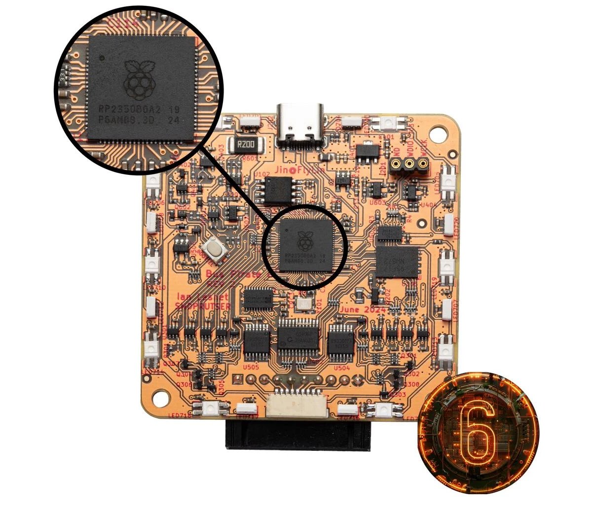
| Bus Pirate 6 | Aug 2024 | RP2350B | The current flagship. RP2350B is the 80-pin QFN variant of RP2350 with 18 extra GPIOs over the RP2350A. Those extra GPIOs are what enable the look-behind buffer (§ 3.2). |
Critical for navigating community docs: most “Bus Pirate” tutorials older than 2024 assume v3.6 hardware — they reference PIC peripherals that don’t exist on the RP2040/RP2350 ports. The firmware language and bus command syntax look similar enough to confuse beginners. When in doubt, check whether a doc mentions pic.h (= old, ignore) or pico/stdlib.h / RP2040 / RP2350 (= current).
1.2.2 Where the BP6 sits in the bench
In this lab, the BP6 fills the wired-protocol-debug slot that no other tool covers. Pairing:
- BP6 + Flipper Zero — Flipper handles RF / RFID / NFC / IR / BadUSB / iButton; BP6 handles UART / I²C / SPI / JTAG / SWD / smart card / DDR5 SPD. They overlap on UART (Flipper has a basic GPIO-as-UART bridge) but the BP6 wins for anything beyond a simple console.
- BP6 + HackRF One (porta) — HackRF for RF protocol research; BP6 for wired protocol research. Non-overlapping bands of “protocol depth.”
- BP6 + a real logic analyzer (when one’s on the bench) — the BP6 drives, the analyzer captures. The BP6’s AUX header is designed for exactly this: it’s a parallel tap on IO0–IO7 + GND that lets you keep the BP’s main probe on the DUT while a Saleae or DSLogic taps the same pins.
The BP6 does not replace:
- A real JTAG/SWD debugger for production debug (BP6 is bit-banged JTAG; J-Link / Black Magic Probe / picoprobe are 10–100× faster on flash programming and support SWO/ITM/RTT trace).
- A real multi-channel logic analyzer (BP6 has 8 channels; a Saleae 16 has 16, a DSLogic has up to 32).
- A real oscilloscope for analog-domain work — the BP6’s per-pin ADC is for slow voltage measurement, not signal-integrity analysis.
But it is the right answer for: “I have an unknown board with header pads. I want to find what speaks what, dump the firmware, and identify the chips,” done in under an hour without writing any custom code.
1.3 BP5 vs BP5XL vs BP6 — the comparison that matters
All three are produced simultaneously by Where Labs and run the same firmware tree (github.com/DangerousPrototypes/BusPirate5-firmware) with per-board CMake targets. The hardware differences are real but not large enough to invalidate cross-version docs.
1.3.1 Hardware deltas
Table 2 — 3.1 Hardware deltas
| BP5 REV10 | BP5XL | BP6 REV2 (this unit) | |
|---|---|---|---|
| MCU | RP2040 (dual Cortex-M0+, 125 MHz) | RP2350A (dual M33 + dual RV) | RP2350B (80-pin QFN, dual M33 + dual RV) |
| SRAM | 264 KB | 520 KB | 520 KB |
| PIO blocks / state machines | 2 / 8 | 3 / 12 | 3 / 12 |
| Architecture options | ARM only | ARM-M33 or RISC-V Hazard3 | ARM-M33 or RISC-V Hazard3 |
| GPIO usage | 30 GPIO + 2× 74HC595 shift registers | Same as BP5 | 48 native GPIO, no shift registers |
| Logic-analyzer mode | Bit-bang same pins as bus driver | Same | 74LVC8T245 octal buffer taps the bus while driving |
| ADC | RP2040 noisy current sense | RP2350 “fixed” ADC | RP2350 “fixed” ADC |
| Display | 240×320 IPS via ST7789V | Same | Same |
| PSU | 1.0–5.0 V, 0–500 mA programmable | Same | Same |
| Per-pin level shifters | 74LVC1T45 × 8 | Same | Same |
| On-board storage | 1 Gbit SPI NAND | Same | Same |
| RGB indicators | 18× SK6812 | Same | Same |
| USB | USB-C | Same | Same |
| Probe header | TJC8A 10-pin keyed locking | Same | Same |
| AUX header | 9-pin 1 mm SH | Same | Same |
| Price (DirtyPCBs) | $42.50 | $63.50 | $82.50 |
The takeaway: same shape, same probe-side electrical interface, same firmware, same UI. The BP6 adds (a) more PIO state machines for concurrent work, (b) more GPIO so shift registers can be dropped from the design, (c) a fixed ADC for cleaner current-sense measurements, and (d) the one feature that actually matters — the look-behind buffer.
1.3.2 The look-behind buffer — BP6’s one defining feature
On the BP5 and BP5XL, the 8 I/O pins are bidirectional and each pin’s drive and sample are time-multiplexed by firmware. When the BP is driving a bus (writing a byte over SPI, transmitting on UART), it cannot simultaneously sample the bus on the same pin. You can interleave drive and sample in software, but you can’t do both at once — which means you cannot use the same BP5 to actively run a flash dump and watch the SPI bus go by on a logic-analyzer view at the same time. You have to choose.
The BP6 fixes this by adding a 74LVC8T245 octal level-translator buffer to the design. The buffer has eight input channels — one wired to each of IO0–IO7, in parallel with the existing 74LVC1T45 per-pin level shifter that drives the pin. The output side of the 8T245 connects to eight extra GPIOs on the RP2350B (the 18-pin GPIO expansion over the RP2350A is precisely what makes this possible — there weren’t enough free pins on the RP2350A to wire it up).
In firmware, this means a PIO state machine on a dedicated set of GPIO inputs can sample IO0–IO7 continuously and in parallel while the mode driver is actively driving the bus from the original GPIOs. The result: simultaneous bus drive and bus capture, all in one device, with the same probes on the same target.
Practical consequences:
- Logic-analyzer-view of an active flash dump session. Run
flash dumpon a SPI flash chip while a PulseView-like UI captures the SCK/MOSI/MISO/CS traffic for verification. Impossible on BP5. - Glitch / fault-injection development where the BP drives a target while a separate PIO state machine watches the response in real time.
- Faster
flash dumpthroughput on 25-series NOR — community measurements cite 2-3× speedups vs BP5 because the SPI driver no longer time-shares its pins with shift-register-multiplexed control signals.
For most casual workflows the look-behind buffer is invisible — you use the BP6 the same way you’d use a BP5. It’s the new capability ceiling that matters: if a future workflow needs sampling-while-driving, only the BP6 supports it. Vol 2 § 5 walks the schematic-grade detail of how the 8T245 is wired and how the firmware enables it. Vol 9 § 3 has the practical “flash dump with parallel capture” workflow.
1.3.3 Pricing and availability
As of mid-2026:
- BP5 REV10 — $42.50 (DirtyPCBs); broadly stocked at Lab401 (EU), KSEC Solutions (UK), Blinkinlabs, The Pi Hut, Hacker Warehouse, Adafruit.
- BP5XL — $63.50 (DirtyPCBs); effectively obsoleted by the BP6 within months of launch. Limited retail stock.
- BP6 — $82.50 (DirtyPCBs, currently the sole worldwide source for the BP6 unit itself). Adafruit / Mouser / DigiKey have not picked up the BP6 SKU as of this writing. Lab401, KSEC, Blinkinlabs primarily stock BP5.
Adapters and cables ship from shop.buspirate.com (Where Labs’ retail front) regardless of which BP version you have — the probe header is identical.
1.4 What the BP6 actually does — capability matrix
The table below captures the board-level ceiling — what the silicon allows. A given firmware version exposes a subset. Mode list is current as of firmware commit 93aefde (2026-04-07, the version the unit is running).
Table 3 — 4. What the BP6 actually does — capability matrix
| Capability | BP6 supports? | Notes |
|---|---|---|
| UART (any baud 300–4 Mbps) | Yes | Standard, including listen-only / sniffer mode |
| HDUART (half-duplex single-wire UART — LIN, K-Line) | Yes | Listen mode added Mar 2026 |
| I²C (100 kHz / 400 kHz / 1 MHz) | Yes | With per-pin pull-ups |
| SPI (Mode 0/1/2/3, up to multi-MHz) | Yes | Most-used mode by far |
| 1-Wire (DS18B20, iButton, DS24xx, etc.) | Yes | Onboard logic; no external transistor needed |
| 2-Wire (custom protocols, SLE4442 smart cards) | Yes | Smart-card via 2-wire + sle4442 cmd |
| 3-Wire (Microwire-class EEPROMs — 93xx series) | Yes | Less commonly needed; legacy |
| JTAG (target boundary scan, IDCODE, OpenOCD bridging) | Yes | Bit-banged in C; OpenOCD-compatible |
| SWD (ARM serial-wire debug) | Yes | Implemented as a JTAG-mode subcommand; pin-find via bluetag |
| Smart card (ISO 7816, SIM-class) | Yes | Via SIM-and-IC-card adapter plank + HDUART mode |
| DDR5 SPD (offline DIMM SPD read/write) | Yes | Via DDR5 SPD adapter plank + I²C mode |
| MIDI (31.25 kbaud UART) | Yes | UART mode baud preset |
| I²S (audio input / output) | Yes | Less commonly used; lab toy |
| IR (38–56 kHz carrier, NEC / RC5 / Sony, etc.) | Yes | TX and RX; IR Toy compatibility layer |
| LED (WS2812 / SK6812 / APA102 driving) | Yes | Plus on-board 18× SK6812 for status |
| Logic-analyzer simultaneous capture | Yes (BP6 only) | Via 74LVC8T245 look-behind buffer; PulseView client |
| Frequency counter | Yes | On-pin |
| PWM generation | Yes | Multi-channel |
| Programmable power supply | Yes | 1.0–5.0 V, 0–500 mA limit |
| Per-pin voltage measurement | Yes | Via CD4067 + ADC; 0–6.6 V range |
| 5 V drive | No | PSU caps at 5.0 V; per-pin buffers are 5.5 V tolerant on the target side but BP-driven voltage maxes at PSU |
| > 8 protocol channels | No | Hardware limit |
| Real-time / sub-µs deterministic timing | Partial | PIO-based protocols are deterministic; bit-banged JTAG isn’t |
| Full CMSIS-DAP / DAPLink | No | Bus Pirate exposes raw JTAG to OpenOCD, not DAP |
| SWO / ITM / RTT trace | No | Use Black Magic Probe or J-Link for these |
1.5 Hardware at a glance
Deep walk in Vol 2; this is the orientation pass.
- MCU: Raspberry Pi RP2350B — 80-pin QFN, dual ARM Cortex-M33 @ 150 MHz, dual RISC-V Hazard3 cores (only 2 cores run at a time; architecture chosen at boot), 520 KB SRAM, 3 PIO blocks / 12 state machines, hardware FPU, integrated SMPS replaced by an external TI 1.1 V LDO in the BP6 design.
- I/O pins: 8 buffered (IO0–IO7), each with its own 74LVC1T45 1.2–5.5 V bidirectional level translator, 120 Ω series resistor for short-circuit protection, an individually-toggleable 10 kΩ pull-up (gated by an SI2301 PFET, < 1 V V_GS — so even logic-low-on signals can have pull-ups), and per-pin ADC voltage measurement via a CD4067 16-channel analog mux.
- The 74LVC8T245 look-behind buffer (BP6-only): 8 of the RP2350B’s extra GPIOs tap IO0–IO7 in parallel with the per-pin 1T45 buffers. Enables simultaneous drive + sample. See § 3.2 above and Vol 2 § 5.
- Programmable Power Supply (PPSU): 1.0–5.0 V output, 0–500 mA programmable current limit. Current sense via 200 mΩ shunt into an op-amp at ×32 gain. Backflow prevention by a PFET ideal-diode + hFE-matched PNP pair. The RP2350’s “fixed” ADC replaces the RP2040’s noisy current-sense.
- Display: 240×320 IPS LCD via ST7789V (SPI), shows live pin labels + per-pin voltage + PSU current draw — same content as the VT100 status bar on the terminal.
- User input: One 33×33 mm SPST button (with six interchangeable caps in the BP5/6 kit — red, yellow, blue dyed, hydro-dipped carbon fiber, chrome, black — plus a 2 mm hex wrench and spare DIN7991 bolts).
- RGB indicators: 18× SK6812 addressable RGBs (10 MINI-E lit through PCB cutouts at each pin + 8 SIDE-A side-lit) driven by a PIO state machine.
- Main probe connector: 10-pin 2.54 mm TJC8A / HX25418 keyed locking header. Pinout: 1 = VOUT / VREF, 2–9 = IO0–IO7, 10 = GND.
- Auxiliary connector: 9-pin 1 mm-pitch JST SH-compatible (J302). Exposes IO0–IO7 + GND in parallel with the main header. Use as a dedicated logic-analyzer tap.
- USB-C for both power and serial console.
- On-board storage: 1 Gbit (~100 MB usable) external SPI NAND, mounted as USB Mass Storage when the device enumerates — holds config, scripts, logs, captures. Separate from the RP2350’s 128 Mbit program flash.
- Mechanical: injection-molded translucent enclosure, DIN 7991 M3 countersunk bolts.
1.6 Firmware at a glance
Deep walk in Vol 3; this is the orientation pass.
1.6.1 Unified tree, per-board targets
The BP5, BP5XL, and BP6 share one firmware repository: github.com/DangerousPrototypes/BusPirate5-firmware (the repo name retained the “5” but the tagline reads “Bus Pirate Firmware for v5 and above”). One source tree, four CMake build targets:
bus_pirate5_rev8— engineering-sample BP5 (rare)bus_pirate5_rev10— production BP5bus_pirate5_xl— BP5XL (RP2350A)bus_pirate6(alsobus_pirate6_rev2) — BP6 REV2 — the target for this unit
Build system: Pico C SDK + CMake. Hermetic Docker compose build available in the repo. GitHub Actions auto-builds UF2s on every push to main and posts them to a single living forum thread at forum.buspirate.com/t/bus-pirate-5-auto-build-main-branch/20 (last page = latest build). Tagged releases on GitHub are rare; main branch is the release channel.
License: MIT, with optional LGPL3 components (legacy ANSI color codes) that can be disabled at build time with -DUSE_LGPL3=NO.
Maintainers: primarily Ian Lesnet (ian@wherelabs.com), with active community contributors via PRs.
Update mechanism, both paths:
- Software path: type
$at the BP6 CLI; firmware reports the expected UF2 filename and reboots into the RP2350’s BOOTSEL mass-storage mode. TheRPI-RP2drive appears on the host; drop the UF2 onto it. - Hardware path (recovery): unplug USB, hold the recessed BOOTSEL button on the PCB bottom, plug in USB while holding. Same drive appears.
Wrong UF2 on wrong target produces a red-blink fault, but the BOOTSEL is mask-ROM — unbrickable from software.
1.6.2 What firmware commit 93aefde represents
The unit is running 93aefde (main branch, 2026-04-07 11:25:00 UTC, author ian@wherelabs.com). The commit itself is small and benign: it adds # as a line-comment character in the syntax parser so pasted command sequences with # annotations don’t error. The diff touches three files (src/commands.c, src/CMakeLists.txt, src/commands/global/hash.{c,h}, ~52 lines net).
The 3-month window around commit 93aefde has been UI / refactor-heavy rather than protocol-heavy:
- Feb 28 — Full VT100 escape-code handling centralized in one module (refactor).
- Mar 2–4 — Toolbar focus refactor; tab-to-focus; menu bar with F-key support; reusable GUI element framework.
- Mar 6–9 — I²C EEPROM GUI prototype with paging for large EEPROMs; menu-bar color themes.
- Mar 13–16 — HDUART listen mode (passive bus monitoring; PR #295); HDUART 8N1 RX fix.
- Apr 7 —
93aefde—#line-comment support.
No smart-card / DDR5 SPD / JTAG / SWD protocol-level changes in this window — those are stable mature features. The motion is UI polish and the groundwork that will eventually surface every command behind a screen widget. Detail in Vol 3 § 6.
1.7 The unit and adapter kit
The specific hardware this series targets:
- Unit: Bus Pirate 6 REV2 (enclosed). S/N
51A99629A9BF944F— this is the RP2350B’s 64-bit unique chip ID, read from OTPOTP_DATA_CHIPID_*registers, not a vendor-assigned tracking number. The 16-hex-digit format confirms RP2350-class silicon: an RP2040 would return an 8-byte JEDEC ID from flash instead. Firmware running93aefde(above). - Probe Cable Set (
BP5-PROBE-REV2, $9.95) — 10-conductor 22 AWG silicone cable, TJC8A keyed locking connector. Includes 10 starter hooks + 10 milled breadboard pins as bundled accessories. (Marketing copy occasionally calls this the “Premium Probe Cable Kit”; same SKU.) - WSON8 SPI flash adapter ($15.95) — clamshell for 5×6 mm and 6×8 mm WSON-8 (desoldered chips, since WSON is lead-less).
- DIP8 SPI flash adapter ($5.95) — ZIF socket for through-hole DIP-8 flash.
- SOP8 SPI flash adapter ($10.95) — desolder-and-insert socket for 150 mil and 208 mil SOP-8. Not a Pomona-style clip. For in-circuit reading without desoldering, pair with a Pomona 5250 (150 mil) or 5252 (208 mil) clip — separate purchase.
- Auxiliary Cable Set (
BP5-AUXCAB-SET-REV2, $9.95) — taps the 9-pin 1 mm SH AUX header, parallel to the main probe header. - KF141 Quick Connector (Adafruit #6019) — spring-cage push-button terminal block for bare-wire DUT hookups.
Detail on every adapter in Vol 8; flash-adapter pinout (identical across WSON8/DIP8/SOP8) reproduced inline:
Table 4 — Detail on every adapter in [Vol 8](/bus-pirate-6/vol-8/); flash-adapter pinout (identical across WSON8/DIP8/SOP8) reproduced inline
| BP pin | Flash pin | Function | Cable color |
|---|---|---|---|
| IO7 | 5 | MOSI / DI | White |
| IO6 | 6 | CLK | Gray |
| IO5 | 1 | CS | Brown |
| IO4 | 2 | MISO / DO | Purple |
| IO3 | 3 | WP | Blue |
| IO2 | 7 | HOLD | Green |
| VOUT | 8 | VCC | Red |
| GND | 4 | GND | Black |
Cable-color-to-IO mapping is hardware-fixed; IO-to-protocol-role mapping is mode-dependent (no universal “brown = MOSI” rule — that mapping above only applies in SPI mode for the standard 25-series flash chips the adapters target).
1.8 Decision tree — when to use the BP6
When you’re standing at the bench wondering whether to reach for the BP6:
Do you need to drive a protocol the target speaks?
├── Yes — go to next question
└── No: you just want to capture bus traffic passively
    ├── ≤ 8 channels, BP-class voltages   → BP6 standalone in sniffer mode
    └── > 8 channels, or sub-µs precision → Saleae / DSLogic logic analyzer

Is the protocol RF (sub-GHz, Wi-Fi, BLE, etc.)?
├── Yes → HackRF One (RF) or Flipper Zero (RFID/NFC/IR/sub-GHz) — not BP6
└── No (wired protocol) — continue

Is the protocol JTAG/SWD on a known target where you want to step code?
├── Yes, and you need full-speed flash programming → Black Magic Probe / J-Link
└── Yes, but pins are unknown OR it's casual recon → BP6 + `bluetag`

Is it a SPI flash chip you want to dump or program?
├── In-circuit (chip still on board) → BP6 + Pomona 5250/5252 clip
└── Out-of-circuit (chip desoldered)
    ├── SOP-8                          → BP6 + SOP8 adapter
    ├── DIP-8                          → BP6 + DIP8 adapter
    └── WSON-8 (5×6 or 6×8)            → BP6 + WSON8 adapter

Is it I²C, UART, 1-Wire, smart card, DDR5 SPD, MIDI, or I²S?
└── BP6 is the right tool. Start in HiZ, configure mode + pins + PSU + pull-ups, then connect.

Are you doing real-time signal processing or sub-µs timing analysis?
└── BP6 is the wrong tool. Use an oscilloscope.
1.9 Comparison to other lab tools
For a quick “why this and not that” reference. Detail in Vol 11 § 9.
Table 5 — 9. Comparison to other lab tools
| Lab tool | When it wins over the BP6 |
|---|---|
| Saleae 8/16 / DSLogic logic analyzer | More channels (16/32), faster sample rates, better protocol decoders in the host software. But cannot drive any bus. |
| Black Magic Probe / J-Link / picoprobe | 10–100× faster JTAG/SWD flash programming. SWO / ITM / RTT trace. CMSIS-DAP. Production debug sessions. |
| CH341A / RT809H / minipro | Dedicated SPI flash programmer with a built-in socket. Faster on bulk flash work. No protocol coverage beyond what it targets. |
| Oscilloscope | Analog-domain work — signal integrity, eye diagrams, sub-µs timing. The BP6’s ADC is for slow voltage measurement, not signal analysis. |
| Bare ESP32 / Pico with custom firmware | Custom-protocol prototyping where the BP6 doesn’t have a mode. But you have to write C; the BP6 has it ready. |
| Flipper Zero | RFID / NFC / IR / sub-GHz / iButton / BadUSB. The Flipper’s GPIO-as-UART bridge is fine for casual UART; the BP6 wins for anything beyond that. |
| HackRF One | Any RF protocol below 6 GHz. The BP6 is wired-only. |
1.10 Depth indices into Vols 2–12
The rest of the series. Reading order is roughly top-to-bottom for newcomers, but each volume is independently useful — pick what you need.
-
Vol 2 — Hardware: RP2350B, the Look-Behind Buffer, and the Per-Pin Level Translators. Schematic-grade. Walks the MCU, the per-pin 74LVC1T45 chain, the look-behind 74LVC8T245, the PPSU op-amp current sense, the CD4067 voltage-measurement mux, the on-board NAND, the LCD interface, and the SK6812 RGB chain. Read this if you’re going to modify the hardware, design a custom plank, or you just want to know exactly what’s behind the 8 probe pins.
-
Vol 3 — Firmware Architecture: PIO State Machines, Mode Vtables, and the Build Tree. How the source code (
pirate/,mode/,commands/,binmode/) maps to silicon. The PIO programs (hwuart.pio,hwi2c.pio, etc.) and why JTAG/SWD are deliberately bit-banged in C rather than PIO. CMake target layout. Read this before building custom firmware. -
Vol 4 — The Syntax Language and the VT100 / On-Screen UI. The complete syntax language:
[ ]transactions,r:N,:Nrepeat, partial-byte read/write (r.4,0x5a.4), delays (d,D), macros, mode-switching, the$BOOTSEL command. The VT100 status bar and the on-screen ST7789V mirror UI. Read this first if you’re going to use the BP6 every day. -
Vol 5 — Power and Probing: PSU, Pull-ups, Voltage Measurement, Pin Discovery. The PPSU 1.0–5.0 V / 0–500 mA range, the per-pin pull-up management, voltage measurement via the CD4067 mux, the frequency counter, PWM generation. The blueTag pin-find scan procedure (lives here even though it’s a JTAG-mode subcommand — the topic is pin discovery, which is mode-agnostic).
-
Vol 6 — Protocol Modes I — UART, HDUART, I²C, SPI. The four daily-driver modes. UART baud-hunt procedure, HDUART listen-mode (LIN / K-Line / single-wire automotive), I²C scan + EEPROM workflows, SPI flash-dump end-to-end. Most days you live in this volume.
-
Vol 7 — Protocol Modes II — JTAG/SWD (blueTag), 1-Wire, Smart Card, I²S, IR, LED. The less-frequent modes. The blueTag JTAG/SWD pin-finder (BP-exclusive feature). 1-Wire iButton + DS18B20 + DS24xx EEPROM. SLE4442 secure-memory cards + ISO 7816 SIM-card dump via the IC card adapter. I²S audio, IR Toy compat, addressable-LED driving.
-
Vol 8 — The Adapter Ecosystem (Probe Cable, WSON8/DIP8/SOP8, KF141, Aux, Planks). Engineer-grade detail on every adapter in the kit: pinouts, mechanical, voltage handling, common-target chip families. The KF141 connector spec. The Auxiliary Cable Set pin map. Plus the broader Where Labs plank ecosystem — DDR5 SPD plank, SIM-and-IC-card adapter, PS/2 sniffer plank, the Blank Plank for custom designs.
-
Vol 9 — Workflows: SPI Flash Dump, EEPROM, JTAG Pin-Find, DDR5 SPD, Smart Card. End-to-end practical recipes. The clip-on-vs-desolder decision tree for SPI flash. The full
flash dump+flash verifyworkflow. The 24-series I²C EEPROM dump. The blueTag JTAG pin-find procedure with the OpenOCD handoff. The DDR5 SPD offline-DIMM workflow. SLE4442 read / write / PSC authentication. -
Vol 10 — Binary Mode and Python Automation: BBIO Legacy and BPIO2 (FlatBuffers + COBS). Host-side scripting. When to use legacy BBIO (flashrom / avrdude / pyBusPirateLite compatibility) versus modern BPIO2 (FlatBuffers + COBS — clean schema, multi-language clients). The Python BPIO2 bindings. Building automated test rigs.
-
Vol 11 — Building from Source, Custom Firmware, and Operational Hygiene. Pico SDK + Docker hermetic build. Custom mode authoring. RP2350 errata E9 mitigation. Detailed debugger comparison (BMP / J-Link / picoprobe / CMSIS-DAP). Bench discipline — when to reach for the BP6 vs not.
-
Vol 12 — Cheatsheet (the Laminate-Ready Field Card). One-pagers — the syntax language quick-ref, the mode quick-ref, the flash-adapter pinout, the JTAG/SWD
bluetagcheatsheet, the smart-card commands, the troubleshooting flowchart. Designed to laminate and live in the field kit.
1.11 Resources
Primary sources cited across the series:
- Firmware repo: github.com/DangerousPrototypes/BusPirate5-firmware — MIT-licensed.
- Hardware docs (BP6 REV2 canonical): docs.buspirate.com/docs/hardware/bp6rev2/hardware/
- BP5/5XL/6 hardware overview: hardware.buspirate.com
- Firmware docs (syntax, command reference): firmware.buspirate.com
- Where Labs shop (adapters, planks): shop.buspirate.com
- Forum (auto-build, support): forum.buspirate.com
- Auto-build UF2 thread: forum.buspirate.com/t/bus-pirate-5-auto-build-main-branch/20
- BPIO2 FlatBuffers schema + bindings: github.com/DangerousPrototypes/BusPirate-BPIO2-flatbuffer-interface
- BP6 + enclosure at DirtyPCBs: dirtypcbs.com/store/designer/details/ian/6667
- Lineage / Wikipedia: en.wikipedia.org/wiki/Bus_Pirate
- CNX Software launch coverage (BP5XL/BP6): cnx-software.com
- Hackaday “Walking the Plank” (BP add-on planks): hackaday.com/2024/08/29/walking-the-plank-add-ons-for-the-bus-pirate
Cross-references inside the Hack Tools hub:
- Cross-tool decision matrix:
../../_shared/comparison.md(prose) ·../../_shared/capability_matrix.html(sortable) - Lab discipline:
../../_shared/legal_ethics.md - Project root:
../../CLAUDE.md - Unit narrative:
../00-inventory/bp6.md - MY_GEAR entry:
../../MY_GEAR/inventory.yaml→bus-pirate-6→bp6
End of Volume 1. Volume 2 picks up with schematic-grade hardware detail — the RP2350B subsystem, per-pin level translators, the look-behind buffer, the PPSU, the CD4067 voltage mux, the NAND, the LCD, and the SK6812 chain.
Comments (0)