DSTIKE Hackheld · Volume 4
DSTIKE Hackheld Volume 4 — Power, Battery, USB-Serial
The 1000 mAh runtime envelope, charge cycle, brownout posture, and CH340 enumeration
4.1 The power tree
USB-C 5V ──► TP4056 ──► LiPo cell (3.0–4.2V) ──► AMS1117-3.3 ──► 3.3V rail
              │             │                                       │
              └── charge    └── protection IC                        └── ESP8266 + OLED + CH340 logic
                            (DW01/8205A or integrated)
Three rails functionally:
- 5V from USB-C (when plugged in) — feeds the charge IC and nothing else.
- Cell voltage 3.0–4.2V — comes off the cell, gates through the protection IC. This is the rail the LDO sees.
- 3.3V regulated — feeds the ESP8266, the OLED logic, and the CH340.
Critical design choice: the chip + display run only from the LiPo (via the LDO), never directly from USB-C 5V. So unplugging USB has zero effect on running operation — you transition seamlessly from “charging + powered” to “running on battery”. The chip never sees a brownout from the USB unplug (the LDO continues providing 3.3V from the cell).
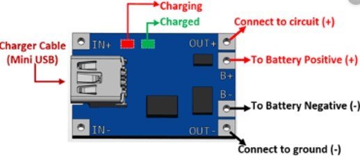
Figure 4.1 — TP4056 charge module and pinout. Source: microcontrollerslab.com.
4.2 Charge cycle
The TP4056 is the canonical $0.10 single-cell linear charger. It runs a textbook CC/CV (constant-current / constant-voltage) profile:
Table 1 — The TP4056 is the canonical $0.10 single-cell linear charger. It runs a textbook CC/CV (constant-current / constant-voltage) profile
| Phase | Cell voltage | Charge current | Duration (1000 mAh from empty) |
|---|---|---|---|
| Pre-charge | 2.5 – 3.0 V | 100 mA (10% of full rate) | < 10 min (recovering deep-discharged cells) |
| Constant-current | 3.0 – 4.2 V | 500 mA (set by RPROG on the board) | ~90 min |
| Constant-voltage | 4.2 V (held) | tapering 500 → 50 mA | ~30 min |
| Terminated | 4.2 V | < 50 mA | done |
Full charge from empty: ~2 hours. The on-board LED (if present — Hackheld V1 has a small status LED somewhere on the back PCB; verify on the bench) indicates charging state — red while charging, blue / green when complete. Some TP4056-based designs have a single LED that just turns off when done; the exact pattern is board-specific.
The TP4056 has no over-temperature monitor of the cell itself. If you charge in a hot environment (>40 °C ambient), the cell heats up additionally during charge, and runaway is the risk path. Charge in cool environments.
4.3 Cell protection
A separate protection IC sits between the cell and the rest of the board. Common implementation is the DW01 (cell-voltage protection) paired with the 8205A dual N-channel MOSFET (which physically gates the cell). Newer designs use an integrated chip (FS312F, etc.) that combines both functions.
Functions:
Table 2 — Functions
| Protection | Threshold | Action |
|---|---|---|
| Over-discharge | Cell voltage < ~2.5 V | Disconnect load — chip and OLED shut off |
| Over-charge | Cell voltage > ~4.3 V | Disconnect charge input |
| Over-current discharge | Discharge > ~3 A | Disconnect for ~200 ms then retry |
| Short-circuit | Discharge > ~10 A | Latch off — requires a brief disconnect of the cell to re-enable |
The over-discharge cutoff is the one users hit. When the LiPo is drained, the protection IC disconnects and the chip dies. Plug in USB-C and the chip comes back to life immediately — the protection re-enables when it sees the cell voltage rise back over the threshold during charging. There is no permanent “the LiPo is dead” failure mode short of physical damage.
4.4 Brownout posture
The ESP8266 has an internal brownout detector (BOD) that resets the chip if VDD drops below ~2.9 V. With a fresh charge at 4.2 V cell + LDO 3.3 V output, you have a lot of headroom. As the cell discharges:
Table 3 — The ESP8266 has an internal brownout detector (BOD) that resets the chip if VDD drops below ~2.9 V. With a fresh charge at 4.2 V cell + LDO 3.3 V output, you have a lot of headroom. As the cell discharges
| Cell voltage | LDO 3.3V output | ESP8266 status |
|---|---|---|
| 4.2 V (fresh) | 3.3 V (clean) | Normal |
| 3.7 V (mid) | 3.3 V (clean) | Normal |
| 3.4 V (low) | 3.3 V (still clean; LDO dropout ~0.1 V) | Normal |
| 3.2 V (very low) | 3.1 V (below LDO regulation, but still above BOD) | Possible Wi-Fi instability |
| 3.0 V (critical) | < 3.0 V | Brownout reset → chip reboots; loops until cell protection cuts in |
The “Wi-Fi instability” zone is where 2.4 GHz TX peaks pull the cell voltage down momentarily — even if average voltage is okay, the instantaneous dip during a deauth-spam burst can drop the rail below BOD threshold. On this unit, this is the practical end-of-runtime: not a clean shutoff but a series of unexpected reboots as the cell gets low.
Mitigation: stop attack workloads when the battery gauge reads ~15% (see Vol 5 § Status bar — the firmware reports battery voltage on the OLED status line).
4.5 Runtime by workload
Estimates for the 1000 mAh cell from 4.2 V to 3.2 V (the practical-usable window — protection cuts in around 3.0 V, but Wi-Fi gets flaky above that):
Table 4 — Estimates for the 1000 mAh cell from 4.2 V to 3.2 V (the practical-usable window — protection cuts in around 3.0 V, but Wi-Fi gets flaky above that)
| Workload | Avg current | Hours |
|---|---|---|
| Idle, OLED off, Wi-Fi off | 5 mA | ~150 |
| Menu navigation, OLED on, Wi-Fi off | 25 mA | ~30 |
| Wi-Fi scan (channel-hopping), OLED on | 80 mA | ~10 |
| Deauth attack, continuous TX, OLED showing status | 250 mA | ~3.5 |
| Beacon spam, continuous TX | 200 mA | ~4.5 |
| Probe spam, continuous TX | 180 mA | ~5 |
These are substantially below the napkin “TX peak × time” estimate because the firmware doesn’t actually TX continuously — even during a deauth attack, there are inter-frame gaps (typical: TX one frame every ~1–10 ms = 0.1–1% TX duty cycle), and during gaps the chip is mostly idle.
Charge cycle for the 1000 mAh cell at 500 mA charge current: ~2 hours from empty to full. So the realistic “day” budget is roughly: 3 hours of attack work, 2 hours of charge, repeat — assuming you have a USB-C source nearby.
For longer field sessions, the answer is either an external USB-C power bank (run the Hackheld off-bank, charging continuously) or a higher-capacity replacement cell.
4.6 Sleep modes that actually work
The ESP8266 supports three sleep modes; each has different practical implications:
Table 5 — The ESP8266 supports three sleep modes; each has different practical implications
| Mode | What’s off | Wake source | Use case |
|---|---|---|---|
| Modem sleep | Wi-Fi PHY only | Any GPIO; immediate | Idle waiting for a button press in a menu |
| Light sleep | Wi-Fi + most peripherals | GPIO 0 only (one specific external pin) | Long-idle UI |
| Deep sleep | Everything except the RTC counter | Wake on RTC timer (preconfigured duration) — pin 16 acts as the wake-pin (must be wired to RST externally) | Wake-once-an-hour sensor-style apps |
Practical caveats for the Hackheld:
- Modem sleep works invisibly: the Wi-Fi stack power-cycles its PHY when idle, the OLED stays on, the chip continues running. Use this in any sketch where Wi-Fi is connected but not actively in use.
- Light sleep with an OLED on is tested-working but the OLED’s I²C bus needs to be quiesced first. Easy to miss; the symptom is a corrupt display on wake.
- Deep sleep with the OLED is awkward — the OLED’s 3.3V comes from the same rail that sleeps. The display latches off cleanly only if you blank it before initiating sleep. GPIO 16 → RST wiring is the standard pattern; verify by inspection on the unit whether DSTIKE wired this (most ESP-12 modules have a pad for it; some boards skip it).
The Spacehuhn firmware does not use deep sleep (it would lose Wi-Fi context on every wake). Custom firmware that does periodic scan + log + sleep can; Vol 11 has a sample.
4.7 USB-CDC over CH340
When you plug the Hackheld into a host:
- The host detects the USB-C connection, polls for descriptors.
- The CH340 enumerates as VID
1A86PID7523(default for CH340N/G; CH340C may report a different PID). - The host loads the
ch341driver and creates a virtual COM port. - The chip’s UART0 (115200 8N1 default) is now mapped to that virtual COM port — bidirectional.
The first time you connect on a new host (especially older macOS), the driver may install in the background; allow 30–60 seconds. Subsequent connections are instant.
What flows over this UART:
| ESP8266 → host | Boot banner, Spacehuhn firmware logs, CLI prompts, debug Serial.print() output |
| host → ESP8266 | CLI commands (Vol 7), Arduino IDE upload data when entering bootloader mode |
The CH340’s DTR + RTS signals are wired through the standard auto-reset RC circuit (a 1 nF cap between DTR and GPIO 0; a similar cap between RTS and EN). When esptool.py or Arduino IDE pulses these lines, the chip is placed in bootloader mode without the user touching the FLASH / RESET buttons. This is the source of “upload just works” in normal operation; when it doesn’t work, the manual button dance is the fallback (Vol 9 § 3).
4.8 Multi-device hosts
If multiple CH340 devices are on the same host — the lineup easily has several — they all enumerate as /dev/ttyUSB0, /dev/ttyUSB1, … in the order they were plugged in. The order is not stable across reboots.
Fixes:
- udev rules on Linux: bind by USB-serial number (the CH340 reports a serial number; most do; some cheap clones report a default
1234and are not uniquely identifiable). - persistent COM port names on Windows: Device Manager → COM Ports → right-click → Properties → Advanced → assign a fixed COM number.
- Just remember which is which: a sticker on each Hackheld noting the COM number works fine if you only have a couple.
For the Hackheld specifically, the strategy that works well: keep the device labelled with its in-use SSID (default pwned) and just look for that SSID before starting an attack — the Wi-Fi mac+ssid + the COM port association is then visually verifiable in seconds.
4.9 Thermal posture
The Hackheld’s thermal envelope under sustained attack:
Table 6 — The Hackheld's thermal envelope under sustained attack
| Workload | Module temperature (steady-state, room ambient) |
|---|---|
| Idle | Room temp |
| Wi-Fi scan | + 2-3 °C |
| Deauth attack (continuous) | + 8-12 °C |
The RF module’s silver can is the thermal mass; it warms perceptibly during attack-spam but does not approach unsafe temperatures (the PA’s thermal-shutdown threshold is well above 100 °C). The LiPo cell is not in thermal contact with the module — it’s on the other side of the PCB with the FR-4 acting as an insulator — so even sustained TX doesn’t cook the cell.
The cell’s own self-heating during charge is the larger thermal concern. Don’t charge in a hot environment (>40 °C ambient).
4.10 What’s next
→ Vol 5 — Spacehuhn WiFi Deauther firmware — the primary firmware deep dive. Architecture, packet-injection model, scan + attack engines, persistent storage, v2.6.1 specifics. The “what’s actually running on the unit out of the box” reference.
Comments (0)