M5Stack Cardputer Zero · Volume 2
M5Stack Cardputer Zero Volume 2 — Hardware
Raspberry Pi CM0 (RP3A0/BCM2837 quad-A53) silicon, ST7789v3 display + 46-key matrix + ES8389 audio + 9-axis IMU, power tree, Cap EXT bus, schematic-style walk of the confirmed Linux pocket computer
2.1 About this volume
Vol 2 walks the confirmed Cardputer Zero hardware at schematic-style depth. The device is a pocket-sized Linux computer built on a Raspberry Pi Compute Module 0 (CM0) — the same silicon class as a Raspberry Pi Zero 2 W — that boots a real OS (Raspberry Pi OS / Debian, aarch64) off a microSD card. Every value below is sourced from the official M5Stack documentation and shop listing plus the Kickstarter campaign (launched 2026-05-26); nothing here is hypothesized.
This is not a microcontroller handheld. There is no firmware to flash, no Arduino sketch, no esptool. The board carries a quad-core ARM application processor, 512 MB of RAM, a real Ethernet PHY, a CSI camera lane, and an HDMI output — a feature set that the budget-MCU framing of earlier drafts got categorically wrong.
Why earlier drafts said ESP32-S3. The original Vol 2 was authored 2026-05-13, before the product shipped, when no spec sheet existed. It reasoned by family pattern: every other Cardputer (original K132, ADV K132-Adv) is an ESP32-S3 device, so a “Zero” budget variant was assumed to be a cost-reduced ESP32-S3 with a smaller battery, a 1.14″ display, a 56-key board, PWM-only audio, no codec, no IMU, no EXT bus, and a ~$30–40 price. That was a plausible-but-wrong textbook extrapolation. The actual product, confirmed on the 2026-05-26 Kickstarter launch, took the name “Zero” from the Raspberry Pi Zero lineage (the CM0 module), not from a budget tier. Every ESP32-derived claim in the old draft is therefore void and has been rewritten below.
For the OS, boot chain, and software stack that this hardware runs, see Vol 3 onward. For the Linux-handheld peers in Jeff’s collection, cross-reference the Cyberdecks project (../../Cyberdecks/ — the Clockwork uConsole is a Pi CM4 Linux handheld of the same cohort; the Zero is the smallest and cheapest of that family).
2.2 Block diagram — confirmed topology
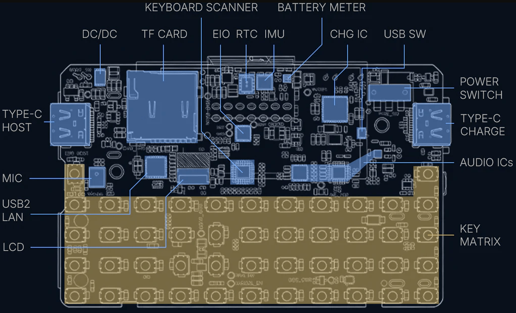
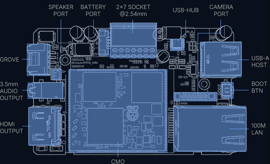
The CM0 (RP3A0 SiP) sits at the center. Its application-processor I/O — SPI, I²C, I²S, SDIO, CSI-2, USB, HDMI/DPI, and GPIO — fans out to the on-board peripheral tree. Unlike an MCU design, most peripherals appear to software as standard Linux devices (a framebuffer/DRM panel, an ALSA card, an input device, a V4L2 camera, an iio IMU, an hwclock RTC), because the CM0 boots a full kernel.
   M5Stack Cardputer Zero — Confirmed Block Diagram
   ════════════════════════════════════════════════════════════════

                       ┌──────────────────────────────────────┐
   microSD ────SDIO────│  Raspberry Pi Compute Module 0 (CM0)  │
   (boot media)        │  ─────────────────────────────────    │
                       │  RP3A0 SiP → BCM2710A1 (BCM2837 die)   │
   IPEX ant ──RF───────│  quad Cortex-A53 @ 1.0 GHz, aarch64    │
   2.4 GHz Wi-Fi       │  VideoCore IV GPU                      │
   BT 4.2 + BLE        │  512 MB LPDDR2 (on-package)            │
                       └───┬───┬───┬───┬───┬───┬───┬───┬───┬───┘
                           │   │   │   │   │   │   │   │   │
        SPI ───────────────┘   │   │   │   │   │   │   │   └──── GPIO ──→ IR TX + IR RX
          └→ ST7789v3 LCD      │   │   │   │   │   │   │
             1.9" IPS 320×170  │   │   │   │   │   │   └──────── DPI/HDMI ──→ HDMI out (≤1080p30)
             + PWM backlight   │   │   │   │   │   │
                               │   │   │   │   │   └────── RMII ──→ 10/100 Eth PHY ──→ RJ45
        GPIO matrix ───────────┘   │   │   │   │
          └→ 46-key keyboard       │   │   │   └──── CSI-2 (4-lane) ──→ IMX219 8 MP cam (Full)
             (scanned → Linux      │   │   │
              input/keyboard dev)  │   │   └──── USB 2.0 ──┬─→ USB-C #1 (host/device switch)
                                   │   │                   ├─→ USB-C #2
        I²S ───────────────────────┘   │                   └─→ USB-A host
          └→ ES8389 codec              │
             ├→ AW8737A amp ──→ 1 W / 8 Ω speaker
             ├→ MEMS microphone        │
             └→ 3.5 mm TRRS jack       │
                                       │
        I²C bus ───────────────────────┴──┬─→ BMI270 (6-axis) + BMM150 (3-axis) = 9-axis IMU (Full)
                                          ├─→ RX8130CE RTC
                                          ├─→ BQ27220 battery fuel gauge
                                          └─→ Grove HY2.0-4P (electronic I²C⇄UART switch)

        Cap EXT 2.54 mm 14-pin header:  SPI · UART · I²C · USB · GPIO · 5V · GND
          └→ optional Cap CC1101 (NFC/sub-GHz), Cap LoRa, etc.

        Power:  USB-C 5V ──→ charger ──→ 3.7 V / 1500 mAh LiPo ──→ rails
                BQ27220 fuel gauge on the I²C bus
Everything in this diagram is present silicon, not a wish-list. The two model tiers differ only in three parts: the Full adds the IMX219 camera, the BMI270+BMM150 IMU, and a bundled 32 GB microSD; the Lite omits those three. Wi-Fi, Bluetooth, Ethernet, HDMI, both USB-C ports, the USB-A host, audio chain, IR, RTC, fuel gauge, Cap EXT bus, and Grove are common to both.
2.3 The Raspberry Pi CM0 — the foundation
2.3.1 The module and its silicon
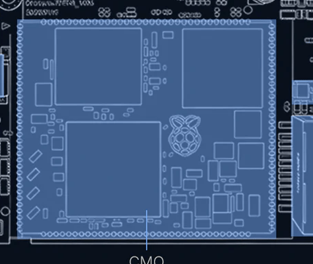
The compute heart is the Raspberry Pi Compute Module 0 (CM0) — the SODIMM-class Pi module built around the Broadcom RP3A0 system-in-package. The RP3A0 is the exact same SiP used on the Raspberry Pi Zero 2 W, so everything the Pi community knows about that board’s SoC, kernel, and userland applies directly here.
Table 1 — 3.1 The module and its silicon
| Aspect | Confirmed value | Notes |
|---|---|---|
| Module | Raspberry Pi Compute Module 0 (CM0) | “Zero” = the Pi CM0 lineage, not a budget tier |
| SiP | Broadcom RP3A0 | Same SiP as the Pi Zero 2 W |
| Die | BCM2710A1 (= BCM2837 family) | M5 docs cite “RP3A0/BCM2837”; CNX cites “BCM2710A1” — same chip, reconciled |
| CPU | Quad-core ARM Cortex-A53, ARMv8-A, aarch64, @ 1.0 GHz | 64-bit application processor, not an MCU |
| GPU | VideoCore IV | OpenGL ES 1.1 / 2.0; hardware video decode |
| RAM | 512 MB LPDDR2 | On-package in the RP3A0 SiP; not upgradeable |
| Boot media | microSD (boots from it) | Full ships a 32 GB card; Lite ships none |
| Wi-Fi | 2.4 GHz 802.11 b/g/n, on-module, IPEX antenna | No 5 GHz on-module |
| Bluetooth | BT 4.2 + BLE | On-module |
| OS | Raspberry Pi OS / Debian, aarch64, off microSD | Full Linux — see Vol 3 |
2.3.2 What the silicon enables
Because this is Pi-class application silicon running a stock kernel, the Zero inherits the entire Raspberry Pi software stack with zero porting effort — it is Pi silicon. Concretely:
- Quad A53 @ 1 GHz, 64-bit aarch64 — runs ordinary Linux binaries:
apt, Python 3, gcc/g++, Rust, Wireshark CLI, nmap, aircrack-ng. Slower than a laptop, but the same software, not a cut-down embedded subset. - 512 MB LPDDR2 — enough for recon, scripting, single-tool runs, and drop-box duty. Not a cracking rig; see Vol 11 for the honest performance envelope.
- Real 10/100 Ethernet PHY → RJ45 — wired networking, the thing the ESP32 framing omitted entirely. A battery-powered box with both Ethernet and Wi-Fi is a credible drop box.
- CSI-2 camera interface — drives the 8 MP IMX219 through the standard
libcamera/ V4L2 stack (Full model). - HDMI / DPI video out — up to 1080p30 to an external display; the device is not limited to its 1.9″ panel.
- USB host — the USB-A port and host-mode USB-C accept keyboards, USB Wi-Fi adapters, SDR dongles, Proxmark clients, etc.
- VideoCore IV GPU — hardware-accelerated compositing for the small-screen Wayland shell (Vol 3).
This is the opposite of the old ESP32 list (“no Ethernet, no camera interface, no 5 GHz, BLE-only, DAC-less”): the Zero has real Ethernet, a real camera lane, HDMI, full Bluetooth 4.2 (Classic + BLE), and a full audio codec.
2.3.3 The one inherited radio limit
The single genuine radio constraint carries over from the Pi Zero 2 W’s RP3A0: the on-module Wi-Fi is 2.4 GHz b/g/n only — there is no 5 GHz and monitor-mode/injection support is driver-limited. For serious Wi-Fi work, attach a known monitor-mode USB adapter via the USB-A host port (Vol 11 covers the operational implications). This is a driver/band limit, not a silicon-class limit, and it is the only major capability the hardware lacks.
2.4 Display subsystem
2.4.1 Display specs
Table 2 — 4.1 Display specs
| Aspect | Confirmed value | Notes |
|---|---|---|
| Size | 1.9″ diagonal IPS LCD | Larger than the original Cardputer’s 1.14″ |
| Resolution | 320 × 170 (landscape) / 170 × 320 native portrait | |
| Type | IPS | Wide viewing angle |
| Controller | ST7789v3 | (One early preview said v2; official docs say v3) |
| Interface | SPI 4-wire (CS, CLK, MOSI, DC) | Driven by a kernel SPI panel driver / DRM |
| Backlight | White LED, PWM-controlled | Software brightness via the backlight sysfs class |
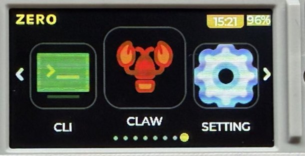
Under Linux the panel presents as a DRM/KMS or fbdev framebuffer; the small-screen Wayland shell (Vol 3 §2b) composites onto it via the VideoCore IV GPU. LVGL apps built with the czdev toolkit target the 320×170 surface directly.
2.4.2 Layout convention
The display sits in landscape (320 wide × 170 tall), long axis matching the keyboard width:
   ┌─────────────────────────────────────┐
   │  ████████████████████████████████   │  ← 1.9" IPS, ST7789v3, 320 × 170
   │  ████████████████████████████████   │
   │  ████████████████████████████████   │
   ├─────────────────────────────────────┤
   │  Q W E R T Y U I O P                │  ← 46-key matrix keyboard
   │  A S D F G H J K L                  │
   │  Z X C V B N M , .                  │
   └─────────────────────────────────────┘
2.4.3 Rendering performance
The display bus is SPI, so full-screen redraw rate is bounded by SPI clock (a 320×170×16-bit frame is ~109 kB; at a typical ~40–60 MHz SPI clock that is tens of frames per second). For the Zero’s real workloads this is ample:
- Text / menu / terminal UI — imperceptible latency.
- LVGL app surfaces (
czdev) — smooth; the GPU composites, the SPI bus only carries the final frame. - Full-motion video — SPI-bound; fine for small clips, not a media centre on the internal panel (use HDMI out for that).
2.5 Keyboard subsystem
2.5.1 The defining Cardputer feature
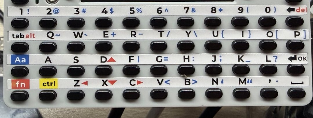
The integrated QWERTY keyboard is what makes a Cardputer a Cardputer rather than a bare Pi module. On the Zero it is a 46-key matrix — note this is fewer than the 56-key board on the ESP32 original/ADV; the count is part of why the Zero’s board layout and footprint differ from the older siblings.
2.5.2 Keyboard implementation
Table 3 — 5.2 Keyboard implementation
| Aspect | Confirmed value | Notes |
|---|---|---|
| Layout | 46-key matrix QWERTY | NOT 56-key (that was the ESP32 Cardputer/ADV) |
| Technology | Membrane matrix under PCB pads | Family construction |
| Scanning | Row/column matrix scan into a kernel input driver | Appears as a standard Linux input/keyboard device |
| Software interface | Linux input subsystem (/dev/input/event*, evdev) | NOT the Arduino M5Cardputer.Keyboard API |
| Modifiers | Shift / Fn / Ctrl / Alt for symbols, function keys, brightness, volume | Fn-layer for the reduced key count |
| Backlit | No |
The critical reframe here is the software model: on the ESP32 Cardputers the keyboard is read by an Arduino library polling the matrix. On the Zero it is a Linux input device — a kernel keyboard/matrix driver scans the rows and columns and emits standard evdev keycodes, so the keyboard works in the console, in the Wayland shell, in SSH-launched TUIs, and in any Linux GUI app with no special library. CJK / complex input is handled by the Fcitx5 bridge (Vol 3 §2b) layered on top of the same evdev stream.
2.5.3 Keyboard layout (46-key)
   ┌────────────────────────────────────────────────────────┐
   │  TAB Q  W  E  R  T  Y  U  I  O  P  BKSP                │
   │  CAPS  A  S  D  F  G  H  J  K  L  ENTER                │
   │  SHIFT Z  X  C  V  B  N  M  ,  .  /                    │
   │  CTRL ALT FN ─────── SPACE ────────  ARROWS  ESC       │
   └────────────────────────────────────────────────────────┘

   46 keys total. Fn-layer provides function keys, symbols,
   brightness, and volume. Exact key assignment: verify on receipt.
2.5.4 Practical considerations
- Typing speed — a thumb-board this size suits short commands, SSH, and config edits, not prose. Adequate for
nmap -sV 10.0.0.0/24andsudo systemctl restart …. - Rollover / ghosting — membrane matrix; rolling chords may not register. Fine for a CLI cadence.
- Console + shell consistency — because it is an evdev device, the same key behaviour holds across the framebuffer console, the Wayland shell, and remote TUIs.
2.6 Audio subsystem
2.6.1 The full audio chain is present
The Zero carries a complete codec-based audio chain — not the PWM-only beeper the ESP32 hypothesis assumed:
- ES8389 audio codec (I²S DAC + ADC)
- AW8737A class-D speaker amplifier
- 1 W / 8 Ω speaker
- MEMS microphone
- 3.5 mm TRRS jack (headphone + mic)
2.6.2 Audio topology
   CM0 I²S ──→ ES8389 codec ──┬──→ AW8737A amp ──→ 1 W / 8 Ω speaker
                              ├──→ 3.5 mm TRRS jack (headphone out + mic in)
                              └──← MEMS microphone (ADC in)

   Exposed to Linux as an ALSA sound card (playback + capture).
Table 4 — 6.2 Audio topology
| Aspect | Confirmed value | Notes |
|---|---|---|
| Codec | ES8389 | I²S DAC + ADC |
| Amplifier | AW8737A class-D | |
| Speaker | 1 W / 8 Ω | |
| Microphone | MEMS | Capture path present |
| Jack | 3.5 mm TRRS | Headphone out + mic in |
| Linux interface | ALSA sound card (aplay/arecord, PulseAudio/PipeWire) | Standard Linux audio |
2.6.3 What this means operationally
Because the chain terminates in an ALSA card under Linux, the Zero supports the full range of audio use that the ESP32 hypothesis ruled out:
- Playback — UI sounds, media (
mpv,StreamPlayer,LoFiBox-Zero), TTS. - Capture — voice recording, audio FFT/spectrum (
AudioSpectrumapp), anyarecord-based pipeline. - Headphone monitoring — via the 3.5 mm jack, including mic-equipped headsets (TRRS).
No feature here is gated by missing hardware; it is gated only by what Linux audio software you install.
2.7 Power topology
2.7.1 Power tree
   USB-C 5V Vbus (either USB-C port)
        │
        ▼
   ┌─────────────┐
   │ Charger     │  Li-ion charge management, USB-C input
   └──────┬──────┘
          │
          ▼
   ┌──────────────────────┐
   │ LiPo cell            │  3.7 V nominal, 1500 mAh, 1S
   │ + BQ27220 fuel gauge │  I²C state-of-charge / current / voltage
   └──────┬───────────────┘
          │
          ▼
   ┌─────────────┐
   │ Regulators  │  CM0 core + I/O rails, 5V bus for USB-A host + Cap EXT
   └──────┬──────┘
          │
          ├──→ CM0 (quad A53 + Wi-Fi/BT) — dominant draw; ~2.5 W idle
          ├──→ ST7789v3 display + PWM backlight
          ├──→ Ethernet PHY (when link up)
          ├──→ Audio amp (AW8737A, varies with output)
          ├──→ USB-A host port (5V to attached devices)
          ├──→ Cap EXT 5V pin + Grove
          └──→ Camera / IMU (Full)
2.7.2 Power model — Linux, not MCU
Table 5 — 7.2 Power model — Linux, not MCU
| Aspect | Confirmed value | Notes |
|---|---|---|
| Battery | 3.7 V / 1500 mAh LiPo, 1S | NOT the 500–1000 mAh the old draft guessed |
| Fuel gauge | BQ27220 (I²C) | Accurate state-of-charge to software |
| Charging | USB-C | Recommend a 5 V / 2 A supply |
| Idle draw | ~2.5 W | Pi-class SoC floor — no µA MCU deep-sleep |
The power model is fundamentally different from an ESP32 handheld. There is no microcontroller deep-sleep that drops the device to microamps; a Linux SoC has an idle floor of ~2.5 W with the CPU clocked down. Power management is the Linux way:
- CPU frequency governors (
ondemand,powersave,performance) trade clock for current. - Display blanking / DPMS and backlight PWM are the largest discretionary savings.
- Disabling unused radios (
rfkill) and the Ethernet PHY when unused. - Suspend-to-idle where supported, but expect runtime measured in hours, not the days an MCU sipping in deep-sleep would manage.
Because the BQ27220 reports real state-of-charge over I²C, the OS can show an accurate battery percentage and time-to-empty — see Vol 5 for the measured power profile per workload. Recommend a 5 V / 2 A source for charge-while-busy; a weak 5 V / 1 A supply can brown out under simultaneous Wi-Fi TX + USB-A load + charging.
2.8 Sensors, RTC, and IR
The old draft’s “sensors likely absent” premise was wrong. The confirmed inertial, timekeeping, and IR hardware:
2.8.1 9-axis IMU (Full model)
- BMI270 — 6-axis accelerometer + gyroscope.
- BMM150 — 3-axis magnetometer.
- Together a 9-axis motion + orientation + heading solution, on the I²C bus, exposed through the Linux IIO subsystem (
/sys/bus/iio/).
This enables tilt/orientation UI, motion logging, and compass heading (useful for the trail-mate outdoor app). The Lite model omits the IMU (and the camera).
2.8.2 Real-time clock
- RX8130CE RTC on the I²C bus — battery-backed wall-clock time, read/set via
hwclockand the kernel RTC class. Important on a Linux box that may boot without network time; keeps timestamps sane for capture logs andcron.
2.8.3 IR
- IR transmitter and receiver — both present, on GPIO. Under Linux these are driven through the LIRC / kernel IR stack (
gpio-ir-tx/gpio-ir), not the ESP32 RMT peripheral. Useful for IR remote capture/replay.
2.8.4 Sensor summary
Table 6 — 8.4 Sensor summary
| Sensor | Lite | Full | Linux interface |
|---|---|---|---|
| BMI270 6-axis IMU | — | Yes | IIO |
| BMM150 magnetometer | — | Yes | IIO |
| RX8130CE RTC | Yes | Yes | kernel RTC / hwclock |
| IR TX + RX | Yes | Yes | LIRC / kernel IR |
| IMX219 camera | — | Yes | libcamera / V4L2 (CSI-2) |
2.9 Mechanical + thermal
2.9.1 Enclosure
Table 7 — 9.1 Enclosure
| Aspect | Confirmed value | Notes |
|---|---|---|
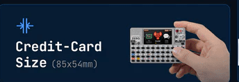
| Dimensions | 84.0 × 54.0 × 23.1 mm | Credit-card footprint, ~23 mm thick |
| Form factor | Pocket / credit-card class | Thicker than the ESP32 Cardputers (battery + CM0 + connector stack) |
| Material | Plastic shell (verify exact resin on receipt) |
The 23.1 mm thickness is notably chunkier than the thin ESP32 Cardputers — it has to house the 1500 mAh cell, the CM0 module standing off the PCB, and the RJ45 + dual-USB-C + USB-A + HDMI connector bank.
2.9.2 Thermal profile
A quad-core Cortex-A53 application processor dissipates meaningfully more than an MCU. Where the old ESP32 estimate was ~0.5–0.8 W peak, the CM0 idles around the ~2.5 W mark and climbs under sustained multi-core load:
- Idle / light CLI — case warm to the touch; no concern.
- Sustained 4-core load (compiling,
aircrack-ng, heavy scripting) — the SiP is the hot spot; in a sealed plastic shell expect the case to climb well above ambient, and the kernel may apply thermal throttling (DVFS clock reduction) exactly as a Pi Zero 2 W does under load. - Mitigation — the Linux governor manages it automatically; for sustained heavy work, ventilation or a heat-spreader pad helps, and reducing the
performancegovernor toondemandcaps the worst-case dissipation. This is a real consideration the MCU framing never had to make.
Treat thermal as a mild constraint under sustained multi-core load — not a showstopper, but no longer the non-issue an ESP32 would be.
2.10 Cross-references
2.10.1 Shared mechanicals — Cardputer ADV
The Cardputer ADV deep dive remains a valid reference only for the shared Cap / Grove mechanical accessories — the 2.54 mm 14-pin Cap EXT header footprint and the HY2.0-4P Grove connector are family-common, so ADV Cap modules are mechanically relevant (verify exact electrical/driver compatibility on receipt, since the Zero’s bus is driven by Linux, not an ESP32).
Do NOT use the ADV deep dive for SoC, OS, programming, flashing, or firmware comparisons — the ADV is an ESP32-S3 device, a fundamentally different class of machine. Those comparisons belong to the Linux peers below.
Table 8 — 10.1 Shared mechanicals — Cardputer ADV
| Zero subsystem | Where to look | Notes for Zero |
|---|---|---|
| Cap EXT 14-pin / Grove mechanicals | Cardputer ADV deep dive (shared accessories only) | Same connectors; Linux-driven, not ESP32 |
| SoC / Linux comparison | Cyberdecks project — Clockwork uConsole (Pi CM4) | Same Pi-Linux-handheld cohort |
| Pi software stack / SoC | Raspberry Pi Zero 2 W (shares the RP3A0 SiP) | RPi OS, raspi-config, libcamera, libgpiod apply directly |
2.10.2 Linux / SoC peers — Cyberdecks project
The Zero’s real software-siblings are the Cyberdecks project’s Linux handhelds (../../Cyberdecks/, cyberdecks.fubsypoly.com): the Clockwork uConsole (Raspberry Pi CM4 Linux handheld) and PicoCalc. The Zero is the smallest and cheapest member of that Linux-handheld cohort. For the OS/boot/dev/flashing story, cross-reference those, not the ESP32 Cardputers.
2.10.3 Forward references within this deep dive
- Vol 3 — the Linux OS, boot chain, Wayland shell, and
czdevapp SDK that this hardware runs. - Vol 5 — measured power profile per workload, building on §7.
- Vol 11 — operational posture: the 2.4 GHz Wi-Fi limit, USB-A monitor-mode adapters, and the “it’s a full computer = real attack surface” implications.
2.11 Resources
Raspberry Pi foundational reference (the CM0 shares the Pi Zero 2 W’s RP3A0 SiP)
- Raspberry Pi Compute Module documentation: https://www.raspberrypi.com/documentation/computers/compute-module.html
- Raspberry Pi Zero 2 W (same RP3A0 SiP): https://www.raspberrypi.com/products/raspberry-pi-zero-2-w/
- BCM2837 / Cortex-A53 / VideoCore IV architecture references (Pi 3 family silicon)
Component datasheets
- ST7789v3 LCD controller: Sitronix product page
- ES8389 audio codec: Everest Semiconductor
- AW8737A class-D amplifier: Awinic
- BMI270 IMU + BMM150 magnetometer: Bosch Sensortec
- RX8130CE RTC: Epson
- BQ27220 battery fuel gauge: Texas Instruments
- IMX219 image sensor: Sony (Full model)
M5Stack documentation
- Cardputer Zero product page: https://shop.m5stack.com/ (search “CardputerZero”)
- M5Stack docs: https://docs.m5stack.com/
- CardputerZero GitHub org (OS, shell, AppBuilder): https://github.com/CardputerZero
Linux-handheld peers (cross-reference for OS / SoC / dev — NOT the ESP32 Cardputers)
- Cyberdecks project — Clockwork uConsole (Pi CM4):
../../Cyberdecks/
End of Vol 2. Next: Vol 3 walks the software — the Linux OS image, boot chain, the small-screen Wayland shell, the czdev LVGL app SDK, and the Debian app store that replace the ESP32 firmware story entirely.
Comments (0)