M5Stack Cardputer Zero · Volume 5
M5Stack Cardputer Zero Volume 5 — Power Profile
Confirmed 1500 mAh LiPo + BQ27220 fuel gauge, USB-C charging, a Linux-SoC power model (no MCU deep sleep), and hours-not-days runtime
5.1 About this volume
Vol 5 covers the Cardputer Zero’s power profile. The load-bearing fact: this is a Linux single-board computer in your pocket, not a microcontroller. The Zero is built on the Raspberry Pi Compute Module 0 (CM0 / RP3A0 → BCM2710A1, quad Cortex-A53 @ 1.0 GHz, 512 MB LPDDR2) — the same system-in-package as the Raspberry Pi Zero 2 W — and it boots a full Raspberry Pi OS / Debian aarch64 off microSD (Vol 2 §3, Vol 3). That single fact reshapes everything in this volume: there is no MCU-style µA deep sleep. The power floor is a Linux SoC idling at roughly 2.5 W, so runtime is measured in hours, like a small laptop — not days, like an ESP32 badge.
The battery is confirmed 3.7 V / 1500 mAh with a BQ27220 I²C fuel gauge — telemetry you can read from userspace under Linux. This volume states the confirmed cell, derives the energy budget (≈ 5.55 Wh), gives a per-mode power model anchored honestly to the Pi Zero 2 W (same silicon), recomputes runtime, and lays out field power discipline for a device that has a real filesystem to protect.
Why earlier drafts said “ESP32 / 500–1000 mAh.” The research-baseline series (2026-05-13) was written before the product shipped, from the M5Stack “Cardputer” name and the family’s ESP32-S3 heritage (original Cardputer K132, Cardputer ADV). The plausible-but-wrong textbook assumption was that a “Zero” tier meant a budget ESP32 handheld with a smaller battery (500–1000 mAh, 700 mAh midpoint) and µA-class sleep. The Kickstarter launch (2026-05-26) confirmed the opposite: it is a Pi CM0 Linux computer that draws more power than an ESP32-S3 — so M5Stack fitted a larger 1500 mAh cell, nearly matching the ADV’s 1750 mAh, and there is no microcontroller sleep state to fall back on. One note is enough; the rest of this volume is confirmed-fact.
Cross-reference: the real power siblings are the Linux handhelds in the Cyberdecks project — ../../Cyberdecks/ (Clockwork uConsole = Pi CM4, PicoCalc). The Zero is the smallest/cheapest member of that Linux-handheld cohort, and its laptop-like runtime behaves like theirs, not like the ESP32 Cardputer ADV (Vol 6).
5.2 Battery — confirmed cell
CONFIRMED (CNX-Software, 2026-05-25). Single-cell 3.7 V nominal / 1500 mAh LiPo, USB-C charged, with an on-board BQ27220 fuel gauge for I²C battery telemetry. Energy budget ≈ 5.55 Wh. Source: CNX-Software 2026-05-25.
Table 1 — 2. Battery — confirmed cell
| Aspect | Confirmed value | Notes |
|---|---|---|
| Chemistry | Single-cell LiPo (Li-poly) | Industry standard |
| Capacity | 1500 mAh | Confirmed; NOT the 500–1000 mAh earlier hypothesis |
| Nominal voltage | 3.7 V | Single cell |
| Charge endpoint | 4.20 V | Standard LiPo CC/CV |
| Discharge cutoff | ~3.0 V (protection IC) | Standard |
| Nominal energy | 1.5 Ah × 3.7 V = 5.55 Wh | Reference value for all runtime math in §5 |
| Energy at 4.2→3.0 V avg ~3.7 V | ~5.55 Wh nominal; ~4.8–5.0 Wh usable | After cutoff margin + regulator efficiency (~88 %) |
| Fuel gauge | BQ27220 (TI), I²C | SoC %, voltage, current, temperature readable under Linux (§3.3) |
The 5.55 Wh figure is the anchor for everything downstream. Note this is battery-side energy; the figure the system actually spends it at is the rail load measured at the battery, which the §4 power model gives in watts. Usable energy is meaningfully below nominal: you lose a slice to the ~3.0 V cutoff (the cell still has charge below cutoff, but the protection IC disconnects), and another slice to buck-regulator conversion loss (~10–12 %). Plan around ~5.0 Wh usable, not 5.55 Wh.
5.2.1 Comparison to siblings
Table 2 — 2.1 Comparison to siblings
| Device | Class | Battery | Energy | Power floor | Typical runtime |
|---|---|---|---|---|---|
| M5StickS3 | ESP32-S3 MCU | 250 mAh | 0.9 Wh | µA sleep / ~80 mA active | hours active / days sleeping |
| Cardputer ADV | ESP32-S3 MCU | 1750 mAh | 6.5 Wh | µA sleep / ~100 mA active | many hours / days sleeping |
| Cardputer Zero | Pi CM0 Linux | 1500 mAh | 5.55 Wh | ~2.5 W idle (no MCU sleep) | ~2 h idle, less under load |
| Clockwork uConsole (CM4) | Pi CM4 Linux | 2× 18650 (~7.4 Wh+) | varies | Linux idle | several hours |
The Zero carries nearly as much energy as the ESP32 ADV but spends it far faster, because its floor is a Linux SoC, not a sleeping microcontroller. Capacity-wise it sits between StickS3 and ADV; runtime-wise it behaves like the Cyberdecks Linux handhelds (../../Cyberdecks/), not like its ESP32 cousins.
5.3 Charge subsystem & fuel gauge
5.3.1 Topology
Standard single-cell USB-C LiPo handheld with charge-while-operating, plus a coulomb-counting fuel gauge on the battery node:
   USB-C (5V) ──→ Charger IC ──┬──→ System power path (powers SoC while charging)
   recommend 5V/2A             │
                               ▼
                   ┌──────────────────────┐
                   │  1500 mAh LiPo cell   │
                   │  + protection IC      │
                   └───────────┬───────────┘
                               │  (battery node — current sensed here)
                         BQ27220 fuel gauge  ──I²C──→ SoC  →  /sys/class/power_supply/
                               │
                               ▼
Buck regulator(s) ──→ 5V / 3.3V / 1.8V SoC + peripheral rails- Input: USB-C, 5 V. Recommend a 5 V / 2 A supply — a CM0-class SoC under load plus the LCD backlight, Ethernet PHY, audio amp, and concurrent charging can comfortably exceed 1 A draw; a 1 A phone charger will charge slowly (or not at all under heavy load). 2 A gives margin.
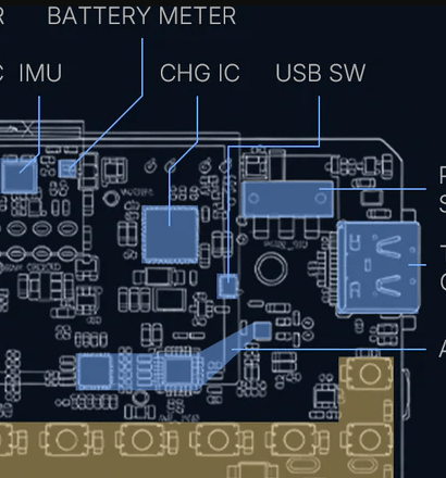
- Charger IC: the specific charger part is not confirmed in published material — verify on receipt (do not assume a TP4056; this is a Pi-class board, more likely a TI BQ25xxx-family charger paired with the BQ27220 gauge). Read the package marking on the unit.
- Fuel gauge: BQ27220 — TI single-cell I²C gas gauge using the Impedance Track / CEDV algorithm. This is the headline power feature: real SoC/voltage/current telemetry, not a crude divider.
- Charge-while-operating: the system runs off the USB-C input while charging, so an external 5 V/2 A pack keeps the cell topped while you work (§6).
5.3.2 Charge time
For a 1500 mAh cell at a ~1 A charge current (typical for this class; the charger may negotiate more):
- CC phase (≈ 3.0 → 4.20 V, ~80 % of capacity): ~70–75 min
- CV phase (4.20 V hold to taper-termination, last ~20 %): ~25–35 min
- Total full charge: ~1.5–2 h at 1 A. Faster if the charger runs ~1.5–2 A (verify the charger IC’s programmed current on receipt).
Charging while the SoC is busy lengthens this — input current is shared between system load and the charge path.
5.3.3 Reading the gauge from Linux (the real win)
Because this is Linux, the BQ27220 is just a power-supply class device. The mainline kernel bq27xxx_battery driver (with its I²C glue) binds it and exposes telemetry under sysfs — no firmware to flash, no custom app:
# Confirm the gauge bound (driver name may read bq27220 / bq27xxx):
ls /sys/class/power_supply/
# e.g. -> bq27220-0   (verify exact node name on receipt)

PS=/sys/class/power_supply/bq27220-0

cat $PS/capacity            # state of charge, %
cat $PS/voltage_now         # µV
cat $PS/current_now         # µA  (negative = discharging on most drivers)
cat $PS/status              # Charging / Discharging / Full
cat $PS/temp                # 0.1 °C units, if exposed
cat $PS/charge_full         # learned full capacity (µAh) — watch this drift down with age
A two-line shell loop turns that into a live power read — multiply voltage_now × current_now for instantaneous watts, which is how you bench-measure the §4 numbers on the actual device:
while :; do
  V=$(cat $PS/voltage_now); I=$(cat $PS/current_now)
  awk -v v=$V -v i=$I 'BEGIN{printf "%.2f V  %.0f mA  %.2f W\n", v/1e6, i/1e3, (v*i)/1e12}'
  sleep 2
done
Tip — anchor the estimates with measurement. Every power band in §4 is marked estimate pending bench measurement. The BQ27220 is exactly how you discharge those question marks: log
current_nowwhile exercising each mode (idle,stress-ngon 4 cores,iw dev … scanin a loop, camera capture) and the §5 runtime table stops being an anchor-to-Pi-Zero-2-W extrapolation and becomes ground truth for this unit. Do this first thing once hardware lands.
5.4 Per-mode power draw (Linux SoC model)
This is a power model in WATTS, not an MCU current table. There is no light-sleep at 20 mA and no deep-sleep at single-digit mA — those were ESP32 fictions. The floor is a Linux SoC. The confirmed idle figure is ~2.5 W; the bands below are engineering estimates pending bench measurement (§3.3), anchored honestly to the Raspberry Pi Zero 2 W, which uses the same RP3A0 SiP as the CM0 (Vol 2 §3).
Honest anchor: a bare Pi Zero 2 W (board only, HDMI/USB idle) measures roughly 0.4–0.7 W idle and ~1.0–1.3 W with all four A53 cores pinned, at the 5 V input.1 The Cardputer Zero’s confirmed ~2.5 W idle is higher because the figure is device-level: it includes the 1.9″ IPS LCD backlight, the ST7789v3 panel, the audio codec/amp, the Ethernet PHY, the RTC, and the buck-regulator conversion losses — none of which exist on a bare Pi Zero 2 W. So treat the Pi Zero 2 W numbers as the SoC delta between modes and add the Zero’s ~2 W of always-on device overhead on top.
Table 3 — 4. Per-mode power draw (Linux SoC model)
| Mode | Est. power (device-level) | Basis / notes |
|---|---|---|
Display off, governor powersave, Wi-Fi/Eth/HDMI off | ~1.5–2.0 W (est.) | The realistic floor — Linux idle, not sleep. No MCU µA state exists. |
| Idle, display on, Wi-Fi associated (no traffic) | ~2.5 W (CONFIRMED) | The published idle figure; backlight + panel + idle SoC + PHYs |
| Light CLI (editor, shell, occasional disk I/O) | ~2.6–3.0 W (est.) | Idle + bursty single-core work + microSD writes |
CPU-bound, 4 cores pinned (stress-ng, compiling, cracking) | ~3.5–4.5 W (est.) | Anchor: Pi Zero 2 W adds ~0.6–0.9 W full-load over idle; + device overhead |
| Wi-Fi active recon (scan/capture, on-module 2.4 GHz radio) | ~3.0–4.0 W (est.) | Radio TX/RX duty + CPU for capture/parse |
| Ethernet + camera active (IMX219 CSI streaming) | ~4.0–5.0 W (est.) | Eth PHY at 100 Mbps + CSI camera + ISP + CPU — heaviest realistic load |
5.4.1 Knobs that actually move the needle (Linux-native)
Because it’s Linux, power management is sysfs/cpufreq/dtoverlay — not firmware sleep modes:
- CPU governor (
cpufreq).ondemand(default) scales 600 MHz ↔ 1.0 GHz with load — good default.powersavepins all cores to the minimum frequency (saves ~0.3–0.6 W at idle-ish loads, at the cost of responsiveness);performancepins max (don’t, on battery).echo powersave | sudo tee /sys/devices/system/cpu/cpu*/cpufreq/scaling_governor cat /sys/devices/system/cpu/cpu0/cpufreq/scaling_cur_freq # confirm - Display backlight PWM. The biggest single always-on load you control. The ST7789v3 panel’s backlight is PWM-dimmable via the backlight sysfs class; halving brightness is a real, continuous saving.
And blank the panel entirely when idle (DPMS /ls /sys/class/backlight/ # find the node (verify name on receipt) echo 64 | sudo tee /sys/class/backlight/*/brightness # of e.g. max_brightness 255vbetool-equivalent /wlopmunder Wayland) — that drops you toward the §4 floor band. - Disable Ethernet when unused. The 10/100 PHY draws whether or not a cable is plugged.
sudo ip link set eth0 down(or blacklist/overlay-disable it) removes that load. Re-enable when you need the drop-box wire. - Disable HDMI/video out. If you’re running headless-over-SSH or on the built-in LCD only, kill the HDMI clock:
tvservice -o(legacy) or the KMS equivalent /dtoverlayto not bring up the HDMI pipeline. Saves the video-out PHY power. - Kill idle radios.
rfkill block wifi/rfkill block bluetoothwhen a wired engagement doesn’t need them. - USB-A host port. Anything you plug into the USB-A host (USB Wi-Fi adapter, RTL-SDR — see Vol 9) draws from the same battery. A monitor-mode USB Wi-Fi dongle can add 0.5–1.5 W on its own; budget for it.
Power saving, biggest lever first (estimates):
  Blank/dim display ........ ██████████  largest continuous knob (backlight)
  Disable Ethernet PHY ..... ████        ~constant when unplugged-but-up
  powersave governor ....... ████        load-dependent
  Disable HDMI out ......... ███          headless/LCD-only
  rfkill idle radios ....... ██           when wired-only
  (No MCU deep-sleep lever — it does not exist on this platform)
5.5 Runtime estimates
Estimates, pending bench measurement (§3.3). Math is usable energy ÷ average power. Battery nominal = 5.55 Wh; usable ≈ 5.0 Wh after the ~3.0 V cutoff margin and ~88 % buck efficiency. Power per mode from §4 (the ~2.5 W idle is confirmed; heavier bands are estimates anchored to the Pi Zero 2 W). Honest bottom line: this is an hours-not-days device — a Linux SoC handheld has laptop-like endurance, unlike an MCU badge that sleeps for days.
Table 4 — 5. Runtime estimates
| Mode | Avg power | Runtime = 5.0 Wh ÷ P | Notes |
|---|---|---|---|
| Idle, display on (confirmed power) | 2.5 W | 5.0 / 2.5 = ~2.0 h | The reference number. ~2 h, not 20. |
Display off / powersave floor | ~1.8 W (est.) | 5.0 / 1.8 = ~2.8 h | Best case; still Linux-idle, not sleep |
| Light CLI work | ~2.8 W (est.) | 5.0 / 2.8 = ~1.8 h | Editing, shell, light I/O |
| Wi-Fi recon (continuous) | ~3.5 W (est.) | 5.0 / 3.5 = ~1.4 h | Scan/capture loop on 2.4 GHz radio |
| CPU-bound, 4 cores | ~4.0 W (est.) | 5.0 / 4.0 = ~1.25 h | Compiling / cracking-lite |
| Ethernet + camera streaming | ~4.5 W (est.) | 5.0 / 4.5 = ~1.1 h | Heaviest realistic load |
Estimated runtime from ~5.0 Wh usable (hours):
  display-off floor   ██████████████  ~2.8 h
  idle (confirmed)    ██████████      ~2.0 h
  light CLI           █████████       ~1.8 h
  Wi-Fi recon         ███████         ~1.4 h
  CPU 4-core          ██████          ~1.25 h
  Eth + camera        █████           ~1.1 h
5.5.1 Realistic mixed-use
Table 5 — 5.1 Realistic mixed-use
| Activity mix | Est. avg power | Runtime |
|---|---|---|
| 70 % idle-display-on, 20 % light CLI, 10 % scan | ~2.7 W | ~1.85 h |
| 50 % CLI, 30 % Wi-Fi recon, 20 % idle | ~3.0 W | ~1.7 h |
| Sustained Wi-Fi pentest workflow | ~3.5 W | ~1.4 h |
| Drop-box: Ethernet up, headless, display off, light logging | ~2.2 W (est.) | ~2.3 h |
Operational bottom line: plan on ~1.5–2.5 hours off the internal cell for active use, under 1.5 h for heavy Wi-Fi/camera/CPU work. This is a multi-hour, not multi-day device. For any engagement past ~90 minutes of real use, carry a USB-C power bank (§6) — running it on the wall or a pack is the normal mode, exactly as you’d treat a small Linux laptop. Do not plan around an MCU-style “sleep it for a week” model; that capability does not exist here.
5.6 Field-deployment power discipline
The Zero is a real computer with a real filesystem — power discipline here is about both endurance and not corrupting the rootfs. Two new rules over the ESP32 mindset: budget for hours not days, and shut down gracefully.
5.6.1 Pre-deployment
- Charge to 100 % (USB-C 5 V / 2 A); verify with
cat /sys/class/power_supply/*/capacity(§3.3). - Carry a USB-C power bank for any engagement over ~90 min of active use — this is the default, not the exception. 5 V / 2 A minimum output; PD/QC is fine (it negotiates 5 V).
- Pack a known-good USB-C cable rated for ≥ 2 A.
- Decide display strategy: dim/blank backlight, run headless-over-SSH where possible (§4.1).
- Decide the shutdown story before you deploy (§6.3) — especially for unattended drop-box use.
5.6.2 During engagement (in priority order)
- Blank or dim the LCD — the single biggest continuous saving (§4.1).
- Disable Ethernet and HDMI if the workflow doesn’t use them — both PHYs draw while up.
- Set the
powersavegovernor for light-load, latency-tolerant work. rfkillidle radios (Wi-Fi/BT) on wired-only engagements.- Stay on external power when you can — charge-while-operating (§3.3) means a pack keeps the cell full while you work; treat internal battery as the transition reserve, not the primary source.
- Watch the gauge (
watch -n30 cat …/capacity); switch to the pack well before ~20 % so a graceful shutdown is always possible.
5.6.3 Graceful shutdown — it’s a real OS (do not yank power)
This is the most important behavioral change from the ESP32 framing. Pulling power on a running Linux system risks microSD/rootfs corruption (in-flight writes, journal, wear-leveling). On an MCU you could just cut power; here you must not.
- Always
sudo poweroff(orsudo shutdown -h now) and wait for the activity LED to settle before disconnecting. Wire a soft-shutdown to a key/GPIO if you’ll be doing it in the field often. - Low-battery auto-shutdown. Because the BQ27220 exposes
capacity/statusto Linux, you can run a small watchdog that triggerspoweroffat a safe SoC (e.g. ≤ 5 %) rather than browning out:# crude low-battery guard (run as a systemd service) while :; do [ "$(cat /sys/class/power_supply/*/capacity)" -le 5 ] && sudo poweroff sleep 60 done - For unattended drop-box duty, make the rootfs resilient to power loss:
- Mount the rootfs read-only (
overlayroot/ Raspberry Pi OS “Overlay File System” viaraspi-config), so a yanked-power event can’t corrupt it; write only to a tmpfs or a dedicated, expendable data partition. - Or run from a minimal read-only image with logs to RAM and periodic flush.
- Mount data partitions with
sync/journaling and minimize write-heavy logging. - This converts the “real OS = corruption risk” liability into “real OS = robust appliance,” and is the standard pattern for Pi-based drop boxes (see Vol 11 operational posture).
- Mount the rootfs read-only (
5.6.4 Engagement-length guidance (external power required sooner than an ESP32)
Table 6 — 6.4 Engagement-length guidance (external power required sooner than an ESP32)
| Active-use duration | Internal cell only? | USB-C pack? |
|---|---|---|
| < 1 h | Yes (with margin) | Optional |
| 1–2 h | Tight (dim/headless to make it) | Recommended (≥ 5 000 mAh) |
| 2–4 h | No | Yes (≥ 10 000 mAh) |
| 4–8 h | No | Yes (≥ 20 000 mAh) |
| All-day / unattended | No | Wall power or large pack + read-only rootfs (§6.3) |
A 10 000 mAh (5 V, ~37 Wh usable) bank is roughly 7× the internal cell — that’s the realistic way to get a Linux handheld through a half-day of work.
5.7 LiPo small-cell safety
The 1500 mAh single cell shares the standard LiPo safety envelope. (Platform-agnostic — the chemistry doesn’t care that the load is now a Linux SoC.)
5.7.1 Standard discipline
- Don’t charge a swollen or puffed cell — retire it.
- Don’t operate or charge when wet.
- Store at ~50 % charge for long shelf life.
- Operating temperature ~0–40 °C; charge ~0–45 °C.
- Charge current ~1C max (≤ 1500 mA for the 1500 mAh cell); the on-board charger sets this — don’t bypass it.
- Discharge cutoff at the protection IC’s ~3.0 V; don’t defeat it.
5.7.2 Cell-specific notes (1500 mAh)
- Discharge ratio is gentle. Peak system draw (~4.5 W ≈ ~1.2 A at the cell) is only ~0.8C on a 1500 mAh cell — comfortably within spec, with modest sag. The larger-than-hypothesized cell is why the platform’s higher SoC draw is sustainable.
- Voltage sag and brownout. A Linux SoC browning out mid-write is worse than an MCU reset — see §6.3. The protection-IC cutoff plus the BQ27220 low-SoC watchdog (§6.3) are your guardrails; honor them.
- Thermal mass. A 5.55 Wh pouch cell warms slowly under ~1 A loads; no special concern at these currents, but keep it out of an enclosed hot pocket during CPU-bound runs.
- Replacement. Verify the exact connector/form factor on receipt before sourcing a spare; M5Stack handhelds often use a model-specific JST-pitch pouch.
5.7.3 Longevity
- ~300–500 charge cycles to ~80 % capacity (typical LiPo). Watch
charge_full(§3.3) drift over time — the BQ27220’s learned capacity is the honest aging signal. - Daily charge → ~1–2 years before noticeable degradation; weekly → ~5+ years.
- Storage (> 2 weeks unused): charge to ~50 %, store at 15–25 °C, disconnect USB (no float stress), top up to ~50 % every few months.
5.8 Resources
- BQ27220 datasheet (TI) — single-cell I²C fuel gauge, Impedance Track / CEDV: https://www.ti.com/product/BQ27220
- Linux
bq27xxx_batterydriver —Documentation/ABI/testing/sysfs-class-power+drivers/power/supply/bq27xxx_battery.c(kernel tree) - Raspberry Pi Zero 2 W power — the same RP3A0 SiP; honest anchor for the §4 SoC deltas (Raspberry Pi docs typical-power notes + community benchmarks)
cpufreqgovernors —Documentation/admin-guide/pm/cpufreq.rst(kernel)- Read-only / overlay rootfs —
raspi-config→ Performance → Overlay File System (for drop-box resilience, §6.3) - Cyberdecks project (Linux-handheld power siblings):
../../Cyberdecks/— uConsole (Pi CM4) and PicoCalc runtime behavior - CNX-Software CardputerZero coverage (battery + spec confirmation, 2026-05-25): https://www.cnx-software.com/2026/05/25/cardputerzero-a-raspberry-pi-cm0-pocket-computer-for-makers/
- Battery University — LiPo behavior canonical: https://batteryuniversity.com/
End of Vol 5. Next: Vol 6 covers the operating-system / software story — writing a Raspberry Pi OS image to microSD, the cardputer-zero-shell Wayland UI, the .deb app ecosystem, and the Linux-native security tooling that replaces the old ESP32 firmware stack.
Footnotes
-
Raspberry Pi Zero 2 W power measurements vary by reviewer and rail; ~0.4 W idle / ~1.0–1.3 W quad-core-loaded at 5 V is the commonly-cited band (e.g. Jeff Geerling’s Pi power benchmarks and the Raspberry Pi documentation’s typical-power notes). The RP3A0 SiP is shared with the CM0, so the core power behavior transfers; the device total does not (different peripherals). Bench-verify on the Zero via §3.3. ↩
Comments (0)